Grinder installation – Grizzly G8183 User Manual
Page 2
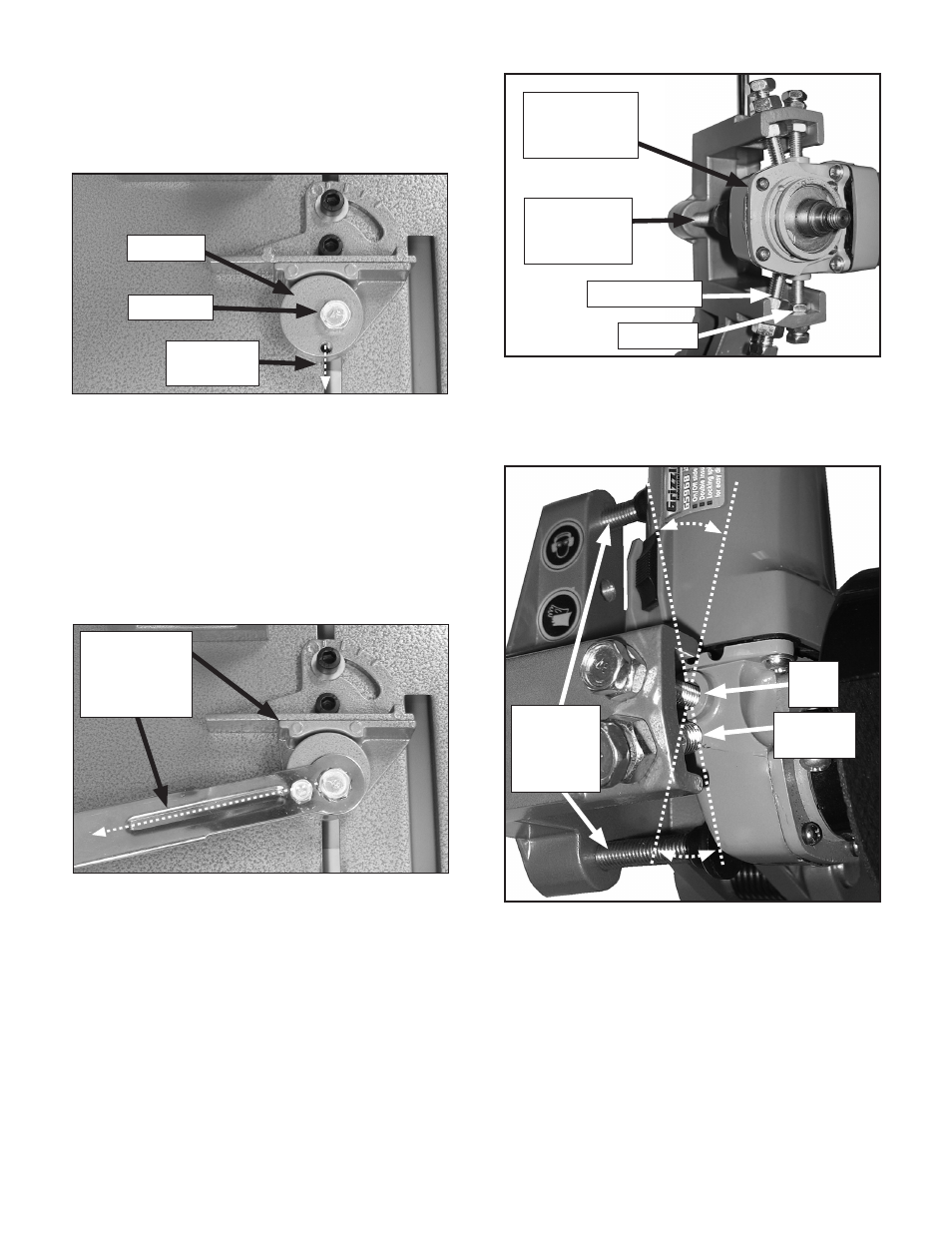
Figure 5. G8183 grinder mounting locations.
3. Finger tighten both stabilizer bolts against the
grinder headstock casting (
Figure 5).
Figure 6. G8183 grinder alignment.
2. remove the lever on the eccentric, loosen
the t-nut bolt so it is just finger tight, then
rotate the cam so the threaded hole is at the
6 o'clock position as shown in
Figure 3.
Figure 3. G8183 quick lock vise.
3. reinstall the lever, and move it to the left so
the cam tightens and both vise jaws clamp
together (
Figure 3).
—If the lever does not clamp the vise jaws
together firmly and stop approximately at
the 8 o'clock position (
Figure 4), repeat
Step 2.
4. Adjust the grinder blade guard so when
the cut will be made, the guard is tilted for
maximum user protection from sparks. refer
to your grinder owner's manual for guard
positioning and spark safety requirements.
5. Alternately thread both of the rubber-foot
alignment studs against the grinder body to
pivot the grinder into alignment for straight
cuts (
Figure 6).
6 o'clock
position
t-Nut Bolt
Grinder Installation
1. position the grinder so the abrasive blade
will enter the slot in the base after the cut is
made.
2. thread both pivot bolts completely into the
holes in the grinder headstock and tighten
the jam nuts (
Figure 5). Note: The hole may
be larger in diameter than the pivot bolts
because these pivot bolts merely serve as
the pivot pins for when the grinder is adjusted
in
Step 5.
Figure 4. G8183 quick lock vise lever.
Vise Locked
and Lever in
the 8 o'clock
position
pivot Bolt
Stabilizer Bolt
rubber Foot
Alignment
Stud
Grizzly Model
5968 Angle
Grinder
pivot
Bolt
rubber
Foot
Alignment
Stud
Eccentric
Stabilizer
Bolt