Generac Power Systems 004945-1 User Manual
Page 7
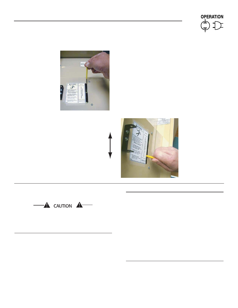
5
• Manual operation handle in the DOWN posi-
tion - LOAD terminals (T1, T2) are connected to
EMERGENCY terminals (E1, E2).
Do not use excessive force when operating the
transfer switch manually or damage could be
done to the manual handle.
3.2.1 CLOSE TO NORMAL SOURCE SIDE
Before proceeding, verify the position of the switch by
observing the position of manual operation handle in
Figure 3.1. If the handle is UP, the contacts are closed
in the NORMAL (UTILITY) position, no further action
is required. If the handle is DOWN, proceed with Step
1.
Step 1: With the handle inserted into the moveable
contact carrier arm, move handle UP. Be
sure to hold on to the handle as it will move
quickly after the center of travel.
Step 2: Remove manual operating handle from move-
able contact carrier arm. Return handle to
storage bracket.
3.2.2 CLOSE TO EMERGENCY SOURCE SIDE
Before proceeding, verify the position of the switch
by observing the position of the manual operation
handle in Figure 3.1. If the handle is DOWN, the
contacts are closed in the EMERGENCY (STANDBY)
position. No further action is required. If the handle
is UP, proceed with Step 1.
Step 1: With the handle inserted into the moveable
contact carrier arm, move the handle DOWN.
Be sure to hold on to the handle as it will
move quickly after the center of travel.
Step 2: Remove manual operating handle from move-
able contact carrier arm. Return handle to
storage bracket.
3.2.3 RETURN TO NORMAL SOURCE SIDE
Step 1: Manually actuate switch to return manual
operating handle to the UP position.
Step 2: Remove manual operating handle from move-
able contact carrier arm. Return handle to
storage bracket.
Section 3 — Operation
ATS “HS” Type Transfer Switch
Attach handle to
the moveable contact
carrier arm.
Move handle UP for the
NORMAL (UTILITY) position.
Move handle DOWN for the
STANDBY (EMERGENCY)
position.
NOTE: Return handle to
storage position in enclosure
when finished with manual transfer.
Figure 3.1 — Actuating Transfer Switch