Global Machinery Company SPJ2HM User Manual
Page 11
11
Note.
For accurate work it is necessary to do a practise cut
first. Check the cut and reset the angle until the correct cut
is achieved.
Variable speed dial
Note.
Adjusting the speed to
suit the application enhances
cutting performance and saves
the blade from undue wear.
To determine optimum cutting
speed, first perform test cuts on
offcuts of the workpiece.
Rotate the dial (8), located at the
back of the jigsaw to set the blade speed (fig S).
Position “1” denotes the lowest speed.
Position “6” denotes the highest speed.
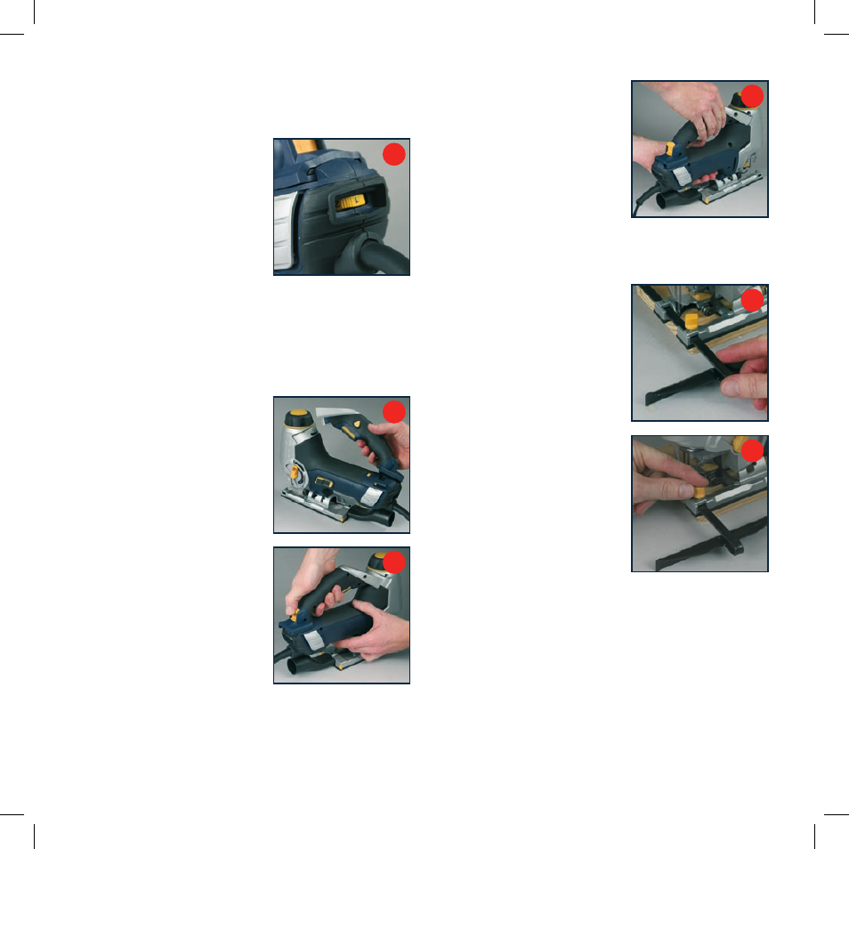
Barrel mode
Note.
The handle (9) can be
removed to allow the tool to be
operated as a barrel jigsaw.
This permits better control when
using the scroll function and
when cutting non-horizontal
workpieces (fig T).
To remove the handle (9) first
grip the handle with the rear
of the saw to the front. Then
use your thumb to lift the
handle release catch (10) and
simultaneously pushing the
handle towards the rear of
the saw.
The handle will slide backwards
and can be removed from
the tool (fig U).
To refit the handle, slide the
handle into position with the
handle locating pin (11) in the
slot at the back of the jigsaw
housing. Push it fully forward
until the handle release catch
(10) locks positively into position
(fig V).
Note.
When not in use, store
the handle in the carry case for
safe keeping.
Parallel guide
Note.
Use of parallel guide (20)
permits accurate parallel cuts,
from an edge, without the need
to mark and follow a pencil line.
The parallel guide can be used
on the left or the right of the
blade. Locate the parallel guide
locking knob (21) on the side that
the fence will be used.
With the parallel guide locking
knob (21) loosened, slide the
guide (20) into the mounting slots
on the shoe plate, from either the
left or right hand side (fig W).
Slide the fence to the required
cut width and tighten the locking
knob to secure the fence
in position (fig X).
Laser sighting
Using the REDEYE
®
laser line system Laser light assembly
The laser light is powered from a transformer housed within
the assembly. The REDEYE
®
laser line can be used for
improved operator cutting vision, accuracy of cut, faster
setup and increased safety of operation.
S
T
U
V
W
X