Gemini ps-02usb User Manual
Page 4
PS-02USB 10" 3 CHANNEL STEREO MIXER
INTRODUCTION:
Congratulations on your purchase of a G
EMINI
PS-02 USB (universal serial
bus)
PROFESSIONAL
10" 3
CHANNEL STEREO MIXER
. This state-of-the-art mixer
features the latest technological advances & is backed by a T
HREE
year war-
ranty, excluding the cross fader. The cross fader is backed by a separate 90
day warranty. Prior to use we suggest that you carefully read all the instruc-
tions.
FEATURES:
- 10" 3 stereo channel mixer
- 8 line inputs, including 6 RCA inputs, 3 convertible phono/line & 2 USB
ports
- Dual USB connectors
- USB connectivity allows mixes to be recorded directly to a compatible PC
or Mac without any additional hardware
- Mix audio files of any format directly from computer (via USB) with
records & CDs
- Both USB playback & recording function can be used simultaneously
- Master, record, & zone RCA outputs
- TRS ¼" balanced outputs
- Triple ground screw for easy connectivity
F
ACE
:
- Removable face plate for user replaceable Rail Glide cross fader
- 3 band EQ kill switches with flash effect
- 3 band rotary line EQ with cut feature & rotary gain channel control
- Lighted push button cue section
- Rotary zone & balance controls
- Dual VU display with bright LED & mode switch
- Master volume fader control
F
RONT
:
- TRS ¼" headphone output & Mic input
- Cue section with rotary Cue volume & Cue/PGM controls with Cue
Split/Mix switch
- Mic section with rotary Mic volume, high & low EQ controls
- Fader section with hamster/reverse, slope, & assign switches
PRECAUTIONS:
1. All instructions should be read before using this equipment.
2. To reduce the risk of electrical shock, do not open the unit. Please refer
all servicing needs to a G
EMINI
-qualified service technician.
3. Do not expose this unit to direct sunlight or a heat source such as a radi-
ator or stove.
4. This unit should be cleaned only with a damp cloth. Avoid solvents or
other cleaning detergents.
5. When moving this equipment it should be placed in its original carton &
packaging. This will reduce the risk of damage during transit.
6. D
O NOT EXPOSE THIS UNIT TO RAIN OR MOISTURE
.
7. D
O NOT USE SPRAY CLEANERS OR LUBRICANTS ON CONTROLS
,
SURFACES OR
SWITCHES
.
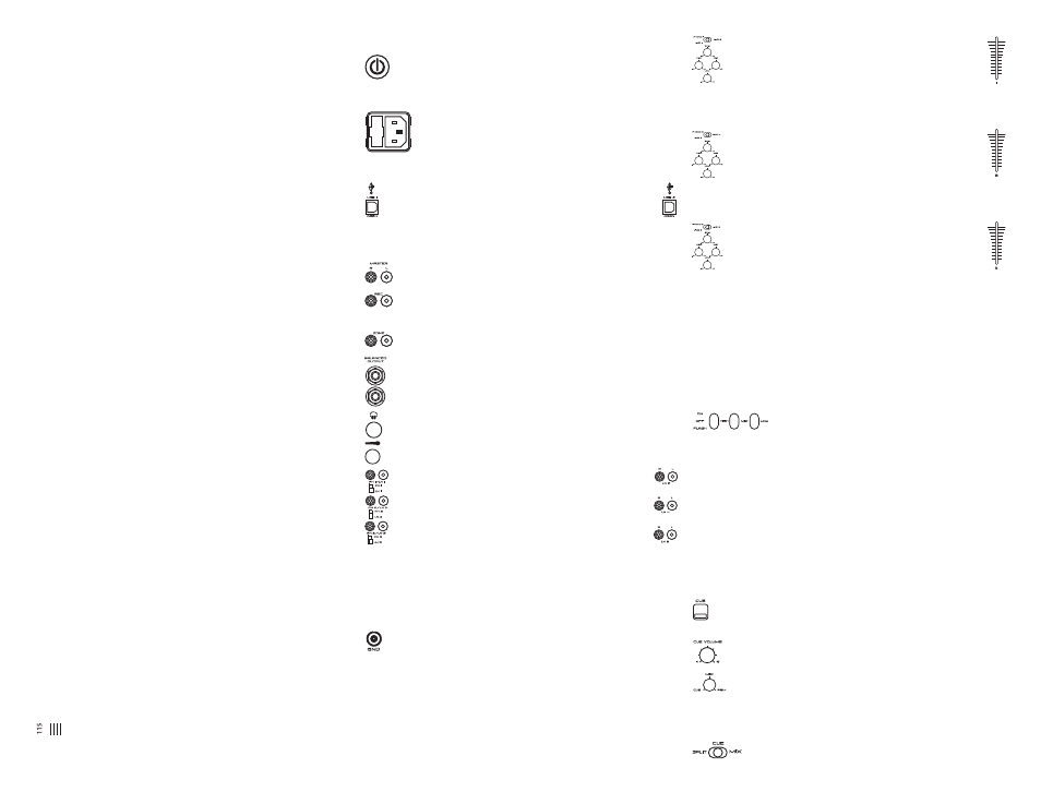
CONNECTIONS:
1. Before plugging this unit into any outlet, make sure that the
V
OLTAGE
S
ELECTOR
(1) is set to the proper voltage. To change the
selection, unscrew the hard plastic protective top with a Phillips head
screw driver. Then use a flat head screw driver to move the switch to the
proper selection (115 V/230 V).
2. Ensure that the P
OWER
S
WITCH
(4) is in the O
FF
position prior to
making any connections. This unit comes with a P
OWER
C
ORD
(2).
Plug the P
OWER
C
ORD
(2) into the rear panel AC
IN WITH
F
USE
(3) jack
before plugging it into a proper power source.
NOTE:
LOCATED BY THE AC IN WITH FUSE
(3)
IS A
250 V
FUSE TO
PROTECT AGAINST ELECTRICAL SURGES
.
TO REPLACE THE FUSE
,
PLACE
A FLAT HEAD SCREWDRIVER INTO THE GROOVE LOCATED INSIDE THE AC
IN WITH FUSE
(3) &
POP THE FUSE OUT
.
REPLACE THE FUSE WITH ONLY
A
250 V
FUSE
.
3. The PS-02 USB has six outputs located on the rear panel:
- The PS-02 USB features two USB P
ORTS
(9, 11) to connect the
mixer to any Mac or PC USB (1.0 or greater) ports allowing the DJ
to either record a session onto any wave form editing software pro-
gram or add computer based DJing or audio programs, .MP3, .WMA, .WAV,
or .AIFF formatted music into the mix. The USB P
ORTS
(9, 11) inputs
receive audio playback signals from a computer.
- The M
ASTER
RCA O
UTPUT
(5) connects the mixer to your main
amplifier using standard audio cables with RCA-type connectors.
- The R
ECORD
RCA O
UTPUT
(6) jacks can be used to connect the
mixer to the record input of your recording unit, thus enabling you
to record your mix with RCA cables.
- The Z
ONE
RCA O
UTPUT
(7) jacks allow the connection of an addi-
tional amplifier with RCA cables.
- The TRS ¼" B
ALANCED
O
UTPUT
(8) connects the mixer to your main
amplifier using standard cables with TRS ¼" connectors. We recom-
mend using balanced cables if the distance to the amplifier is ten feet
or more.
4. Headphones may be plugged into the ¼" jack located in the front
panel’s C
UE
S
ECTION
(21).
5. Microphones may be plugged into the ¼" jack located in the front
panel’s M
ICROPHONE
S
ECTION
(19).
6. The PS-02 USB has 3 C
ONVERTIBLE
P
HONO
/L
INE
(PH/LN) RCA
inputs for channel (CH) 1, CH 2, & CH 3 located on the rear
panel. Facing the rear panel, the convertible RCA input for CH
1 is PH 1/LN 1 (18), for CH 2 is PH 2/LN 3 (16), & for CH 3
is PH 3/LN 5 (14). Using the PH/LN C
ONVERTERS
, located just
below each input, you may convert the input from PH to LN &
vice versa. Plug the RCA's from your playable medium into each input to
be connected to their respective channels. The PH I
NPUTS
only accept
turntables with a magnetic cartridge. The stereo LN I
NPUTS
for CH 1 is LN
2 (17), for CH 2 is LN 4 (15), & for CH 3 is LN 6 (13) only accept line level
inputs such as a CD, DAT, M
INI
D
ISC
, etc. All RCA inputs require the prop-
er LN S
WITCH
(32, 33, 34) setting.
7. When using (a) turntable(s), you will need to ground the RCA
cable(s) by screwing in the grounding fork(s) to the T
RIPLE
G
ROUNDING
S
CREWS
(GND) located in the rear panel of the PS-02 USB mixer. Attach
each PH ground lines to one of the GND. These are located to the right of
each PH/LN C
ONVERTER
.
NOTE:
WHEN USING TURNTABLES
,
NOT ATTACHING A GROUND MAY CAUSE A SYSTEM
"
HUM
."
OPERATIONS:
1. Once all of your connections have been made in the rear panel, turn on
the mixer by pressing the P
OWER
S
WITCH
(4).
2. CH 1: To bring this channel into program output (PGM),
you must first decide which line will be in use. Use the CH 1
LN S
WITCH
(32) to toggle from PH 1/LN 1 (18) to LN 2 (17) on
this channel. Once you've selected the proper line, slowly raise
the CH 1 F
ADER
(23) to a comfortable level. You can further modify the
sound output of this channel by adjusting the rotary G
AIN
, H
IGH
, M
ID
, L
OW
(29) controls located below the CH 1 LN S
WITCH
(32).
3. CH 2: To bring this channel into PGM, you must first decide
which line will be in use. Use the CH 2 LN S
WITCH
(33) to tog-
gle from PH 2/LN 3 (16) to LN 4 (15) on this channel. Once
you've selected the proper line, slowly raise the CH 2 F
ADER
(24) to a comfortable level. You can further modify the sound output of this
channel by adjusting the rotary G
AIN
, H
IGH
, M
ID
, L
OW
(30) controls located
below the CH 2 LN S
WITCH
(33).
4. CH 3: To bring this channel in to PGM, you must first decide
which line will be in use. Use the CH 3 LN S
WITCH
(34) to tog-
gle from PH 3/LN 5 (14) to LN 6 (13) on this channel. Slowly
raise the CH 3 F
ADER
(25) to a comfortable level, once you've
selected the proper line. You can further modify the sound output of this
channel by adjusting the rotary G
AIN
, H
IGH
, M
ID
, L
OW
(31) controls located
below the CH 3 LN S
WITCH
(34).
NOTE:
FOR OPTIMAL PERFORMANCE
,
BEGIN PROGRAM MIX WITH ROTARY GAIN CON
-
TROLS SET TO MINIMUM
&
ROTATE IT TO THE COUNTER CLOCKWISE POSITION
.
MAKE
ALL ADJUSTMENTS IN SOUND OUTPUT WITH THE USE OF YOUR CH FADERS
(23, 24,
25),
ZONE
(37),
BALANCE
(38), &
MASTER VOLUME
(26)
CONTROLS
. T
HIS WILL
PREVENT SIGNAL OVERLOAD
&
DECREASE DISTORTION
.
ONCE YOU HAVE MODIFIED
YOUR SOUND
&
WOULD LIKE TO INCREASE THE OUTPUT OF YOUR SOUND
,
THEN YOU
MAY ADJUST THE ROTARY GAIN CONTROL IF NEEDED
.
5. F
REQUENCY
K
ILLS
: There are two ways to kill, or cancel
out, frequencies, only on CH 2 (24) & CH 3 (25), using
the H
IGH
, M
ID
, & L
OW
F
REQUENCY
K
ILL
S
WITCHES
(28). Each F
REQUENCY
K
ILL
S
WITCH
(28) has 3 positions: O
N
, O
FF
& F
LASH
. When you move the select-
ed F
REQUENCY
K
ILL
S
WITCH
(28) to the top O
N
position, the switch will stay
there, & the frequency will be killed. When you move the selected
F
REQUENCY
K
ILL
S
WITCH
(28) to the center position O
FF
the kill function is
not active, & the frequency will not be killed. When you move the selected
F
REQUENCY
K
ILL
S
WITCH
(28) to the bottom F
LASH
position & hold it there,
the frequency will be killed. Releasing the selected F
REQUENCY
K
ILL
S
WITCH
(28) from the bottom position will bring it back to the center position &
the frequency will no longer be killed.
6. C
UE
S
ECTION
: By connecting a set of headphones to the ¼" jack in the
C
UE
S
ECTION
(21), you can monitor any or all channels.
- C
UE
: Press the C
UE
B
UTTONS
(27) located above CH 1 (23), CH 2
(24), &/or CH 3 (25) to assign the CH(s) to be monitored in your head-
phones. The respective C
UE
LED indicators will glow when in use.
- C
UE
V
OLUME
: Use the front panel located rotary C
UE
V
OLUME
con-
trol to adjust the cue volume without changing the overall mix.
- C
UE
/M
IX
/PGM: By turning the front panel located C
UE
/M
IX
/PGM
rotary control counter clockwise you will be able to monitor the
assigned cue signal. Slowly turning the control clockwise to middle posi-
tion (M
IX
) allows you to monitor your C
UE
signal mixed with PGM. Moving
the control clockwise to the right allows you to monitor PGM output.
- C
UE
S
PLIT
/M
IX
: Use the C
UE
S
PLIT
/M
IX
switch to split the
audio input playing in your head phones. When the C
UE
4