Garrett – GarrettCom Quad User Manual
Page 36
Magnum Quad-Series Fiber Switches
Installation and User Guide (06/09)
29
www GarrettCom com
.
.
Step 8. Once all QPM cards have been installed (including face plates for empty slots),
the chassis cover should be replaced.
3.9.3
Removing QPM Cards
To properly remove a QPM card from the Fiber Switch, follow the 3 steps
below.
Step 1. Remove chassis cover See procedure in Section 3.9.1 above.
Caution: Be sure the power cord is unplugged.
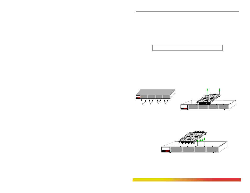
Step 2. Remove bottom-front retaining screws for the QPM and Face Plate
On the bottom-front of the unit there are two retaining screws for each QPM
card and face plate slot. These screws are used to secure a QPM card in
position (see Figure 3.9.3a). Remove the front screws first and then screw
mounted on the rear-top of the QPM to be removed.
Figure 3.9.3a: Front View - Face Plate & QPM Retaining Screws
Step 3. Remove QPM Card
Gently pull the QPM card up and out of the connector socket (see Fig.3.9.3b).
Figure 3.9.3b: Removing a QPM Card
If the slot from which the QPM card has been removed is to remain unused, be
sure to install a QPM face plate cover in it. If another QPM card is replacing
the one that has been removed, follow the steps as described for installing a
QPM card discussed in Section 3.9.1.
GARRETT
Magnum QS5116
Fiber Switch
Two Bottom retaining Screws for each QPM card
1
QPM CARDS
GARRETT
Magnum QS5116
Fiber Switch
J1 J2 J3
J4
Printed Circuit card
TOP
Two retaining screws on the rear top of
module
1
QPM CARDS
J1 J2 J3
J4
Printed Circuit card
TOP
GARRETT
Magnum QS5116
Fiber Switch