GarrettCom Quad User Manual
Page 22
Magnum Quad-Series Fiber Switches
Installation and User Guide (06/09)
15
www GarrettCom com
.
.
3.0
INSTALLATION
Before installing the equipment, it is necessary to take the
precautions as stated on page iii of this User Guide.
Installation: This section describes installation of the Magnum Quad-Series Switches,
as well as connection of the various Ethernet media types.
3.1
Locating Magnum Quad-Series Switches
The location of a Magnum Quad-Series Switch is dependent on the physical
layout of the network. Typically the Switch is placed in a central wiring location where
groups of network devices need to be connected in order to communicate with each
other. These Switches are typically rack mounted in a wiring closet see Section 3.3.2
below), but because they have rubber feet they can also be installed on a shelf or table
top. The compact size of the 8-port QS580 unit allows it to be easily placed in an office
or lab area, and it can also be either shelf of wall-mounted (see Section 3.3.1 below).
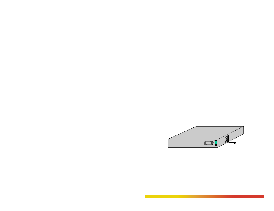
Locate an AC receptacle that is within six feet (2 meters) of the intended
Magnum Quad-Series site. The rugged metal case of the Magnum Quad-Series will
normally protect it from accidental damage in a lab or workplace setting. Maintain an
open view of the front to visually monitor the status LEDs. Keep an open area around
the unit so that cooling can occur from the small fan on the left side, while the unit is in
operation. See figure below.
Figure 3.1: Location of 8-port Magnum QS580’s cooling fan exhaust
3.2
Connecting Ethernet Media
The Magnum Quad-Series Fiber Switches are specifically designed
to support all standard Ethernet media types within a single Switch unit. This
is accomplished by using a family of Quad-port Modules (QPMs) which can be
individually selected and configured per-port. See Section 2.4 for a description
ON
OFF
110-220
VAC
47-63Hz
1.0-0.5A
FAN EXHAUST