Identification – Grizzly G7945 User Manual
Page 10
-8-
G7945/G7946 Radial Drill Press
10
Identification
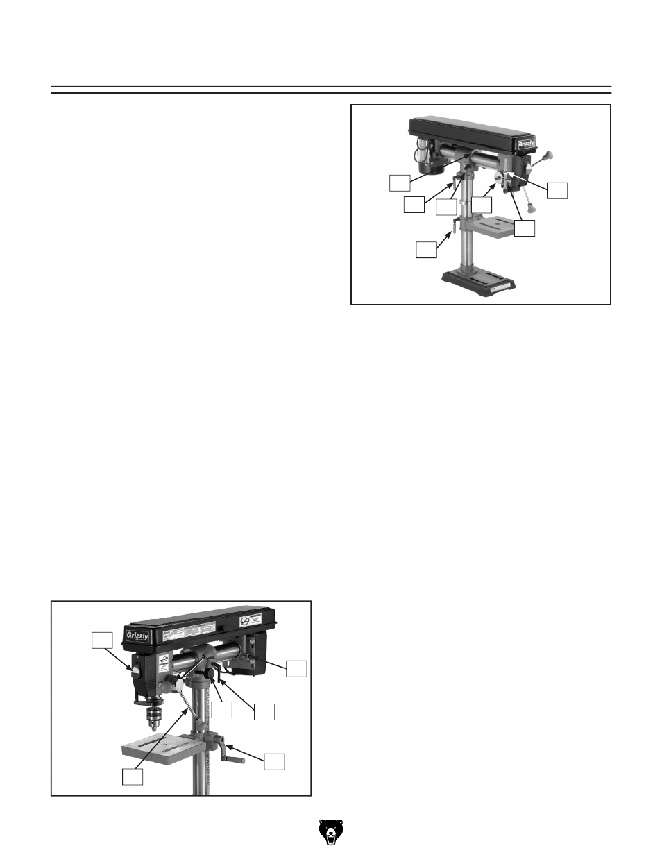
Figure 1. Right-side controls.
Figure 2. Left-side controls.
Refer to the list below and see
Figures 1 & 2 to
become familiar with the drill press controls.
1. Power Switch: Turns motor ON/OFF.
2. Belt Tension Lock Knobs: Locks motor in
place to maintain belt tension.
3. Horizontal Adjustment Lever: Moves the
headstock along the horizontal rack.
4. Clamp Bolts: Lock table rotation, horizontal
movement of drill press, and lock drill press
rotation on column.
5. Crank Handle: Raises/lowers table.
6. Downfeed Handles: Move the chuck up or
down.
7. Depth Stop: Limits quill travel to a pre-set
drilling depth.
8. Lash Screw: Removes quill lash.
9. Torsion Spring: Returns quill into head-
stock.
10. Lock Pin: Locks headstock in the vertical
position. When unlocked, headstock can be
tilted.
11. Headstock Angle Tilt Scale: Displays cur-
rent headstock-tilt angle.
Refer to the list below to become familiar with
the drill press terms and definitions.
Headstock: The cast iron upper portion of the drill
press, which houses the quill and work light, and
supports the motor and belt housing.
Arbor: A tapered shaft that connects the chuck to
the spindle.
Quill: Houses the spindle and bearings.
Spindle: The hollow shaft that accepts the arbor.
11
1
6
5
4
3
2
4
8
4
7
9