Installation, Typical installation drawing – Graco VISCON HP 309524L User Manual
Page 6
Installation
6
309524L
Installation
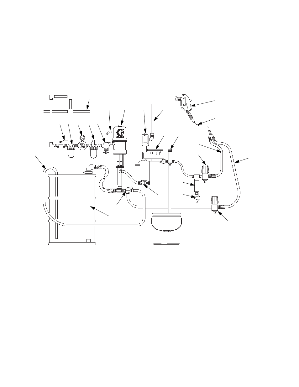
Typical Installation Drawing
The typical installation drawing is only a guide. Your Graco distributor can assist in designing your system.
F
IG
. 1: Typical Installation – Heated Circulating System
Key:
A
Bleed-type Master Air Valve
B
Air Filter
C
Air Regulator and Gauge
D
Air Line Lubricator
E
Pump Runaway Valve
F
Ground Wire
G
Pump
H
Explosion Proof Power Switch
J
Power Cable
K
Heater
L
Fluid Filter
M
Drain Valve
N
Fluid Pressure Regulator
P
Fluid Supply Line
Q
Spray Gun
R
Fluid Return Line
S
Back Pressure Valve
T
Fluid Shutoff Valve
U
Director Valve
V
Drain Back Tube
W
Suction Tube
X
Pressure Relief Valve
Y
Whip End Hose
Z
Air Supply Line
Q
05486-524
Y
R
S
P
N
L
M
T
U
X
K
H
G
F
E
D
C
B
A
V
W
Z
J