Cabinet service procedures – Frymaster 8196606 User Manual
Page 14
Cabinet Service Procedures
2-9
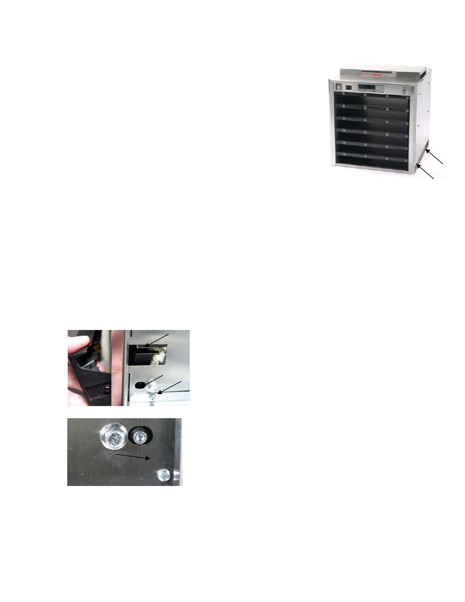
Fig. 7: Two screws (see arrows) at the
base of each side of the cabinet secure
the sides.
3.
HHHH means RTD indicates the temperature is above 255°F (124°C), but below "Open" circuit
resistance, which causes
SENS ALARM.
4.
UHC VERSION _ _ _ (version number will vary)
appears for five seconds when the unit is turned on.
5. The cabinet also displays a variety of error messages, which are
shown on page 3-1.
2.6 Removing/Replacing Bezels
1. Remove power from unit.
2. Remove screws at the base of each side and remove side
panels. (See figure 7.)
3. Unplug the bezel from the distribution board.
4. Plug the replacement bezel into the distribution board,
return power to the unit and test the bezel/cabinet for
accurate operation.
5. Remove replacement bezel and remove power from the unit.
6. Loosen the hex nut which secures the row and remove the allen screw, which holds the
bezel. Also remove, if present, the small bezel-securing screw. (See photo below.)
7. Push, if necessary, on the mounted bezel through the access port in the inner panel to
loosen the bezel. (See Figure 8 below.)
8. Remove bezel; clean and degrease the groove in the heater plate.
9. Route ribbon cable for the new bezel through the inner panel of the cabinet and press the
new bezel into place. Ensure it is firmly seated and tighten hex nuts and replace allen
screws.
10. Return sides and reposition cabinet for operation.
Fig. 8: Loosen the hex bolt and
remove the allen screw (arrows,
upper photo). Some row positions
may have an additional screw
securing the bezel to the cabinet
(lower photo). Push through the
access port (arrow, upper photo), if
necessary, to remove the bezel
from the cabinet .