Cabinet service procedures – Frymaster 8196606 User Manual
Page 11
Cabinet Service Procedures
2-6
2.3 Accessing the Electronic Components
1. The component shelf is accessed by removing two screws on each side of the unit (Fig. 1).
2. Lift and remove the sides, which exposes screws that hold the top in place (Fig. 2).
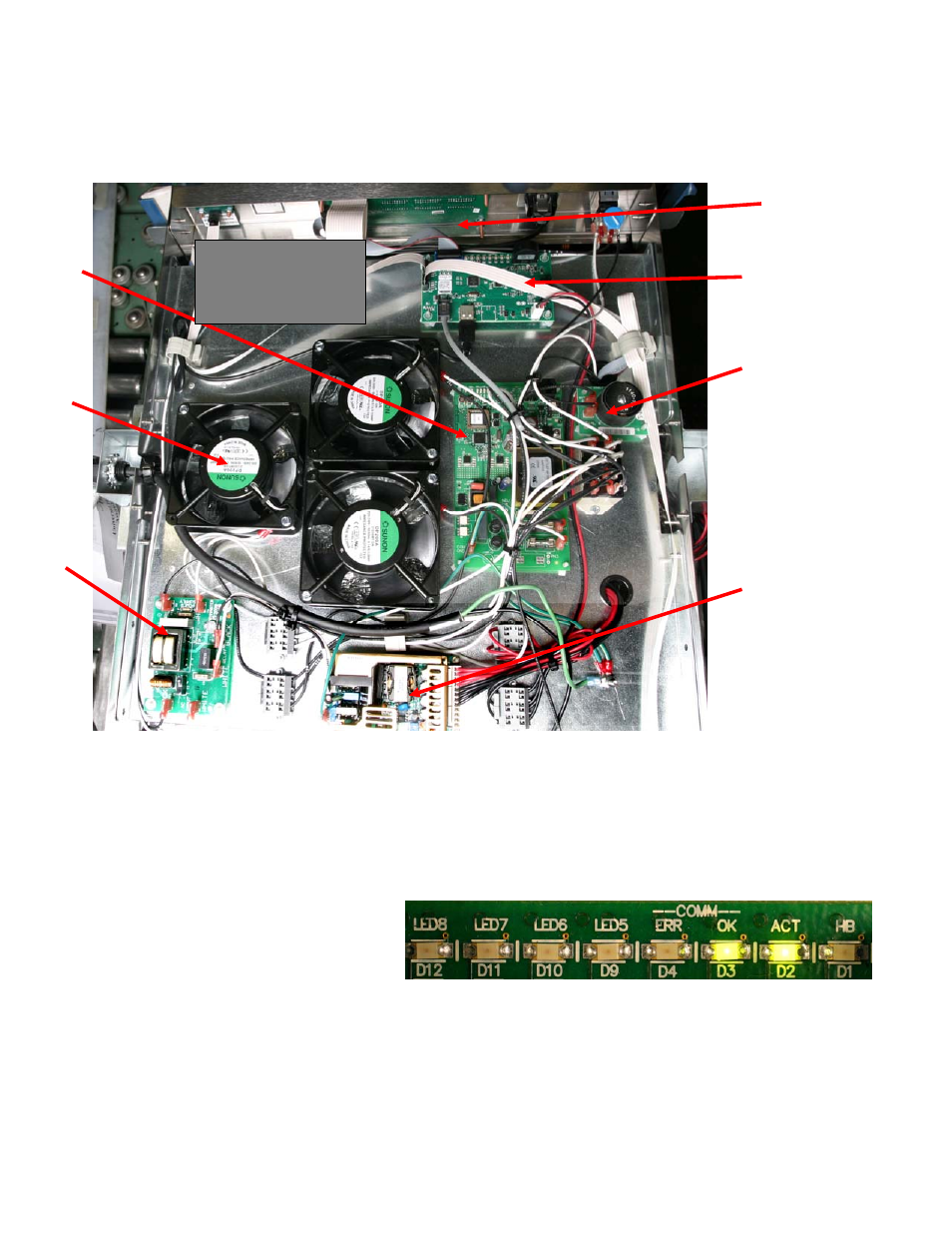
3. The components are annotated below (Fig. 3).
All the components are readily removed. There are no replaceable components on the circuit boards.
2.4 Circuit Board LED Diagnostics
Master Control Board:
• HB LED is a heartbeat; should
be flashing when in the normal
in- use mode. Flash rate is not
critical.
• ACT LED similar to HB but
flashes at a faster rate.
• OK LED toggles each time a valid communication packet is sent and received. Normally a
very fast flicker.
Relay
Fans: are specific to
regions of the cabinet
and ducted to direct
the air flow.
Fig. 4: Master Control Board LED's
Figure 3
Master
Display
Board
LON
filter
Master Control
Board
LON board
LON
filter
Power
supply
Cooling
fans
NOTE: The cooling fans
rest on ducts, and cool
specific regions of the
cabinet.