Mb3788 – FUJITSU MB3788 User Manual
Page 14
MB3788
14
■
■
■
■
HOW TO SET TIME CONSTANT FOR TIMER & LATCH-TYPE SHORT-CIRCUIT
PROTECTION CIRCUIT
If the load conditions of the switching regulator are stable, the outputs of comparators 1 and 2 do not change,
so the SP comparator outputs a High level. At this time, the SCP pin (pin 15) is held at about 50 mV.
If the load conditions change suddenly due to a load short-circuit, for example, the output voltage of the com-
parator of the channel becomes a High-level signal (more than 2.1 V). Then, the SVP comparator outputs a
Low level and transistor Q1 is turned off. The short-circuit protection capacitor C
PE
externally connected to the
SCP pin starts to charge.
V
PE
= 50 mV + t
PE
×
10
-6
/C
PE
0.65 = 50 mV + t
PE
×
10
-6
/C
PE
C
PE
= t
PE
/0.6 (s)
Once the capacitor C
PE
is charged to about 0.65 V, the SR latch is set and the output drive transistor is turned
off. At this time, the duty cycle is made low and the output voltage of the SCP pin (pin 15) is held at Low level.
This closes the SR latch input to discharge C
PE
.
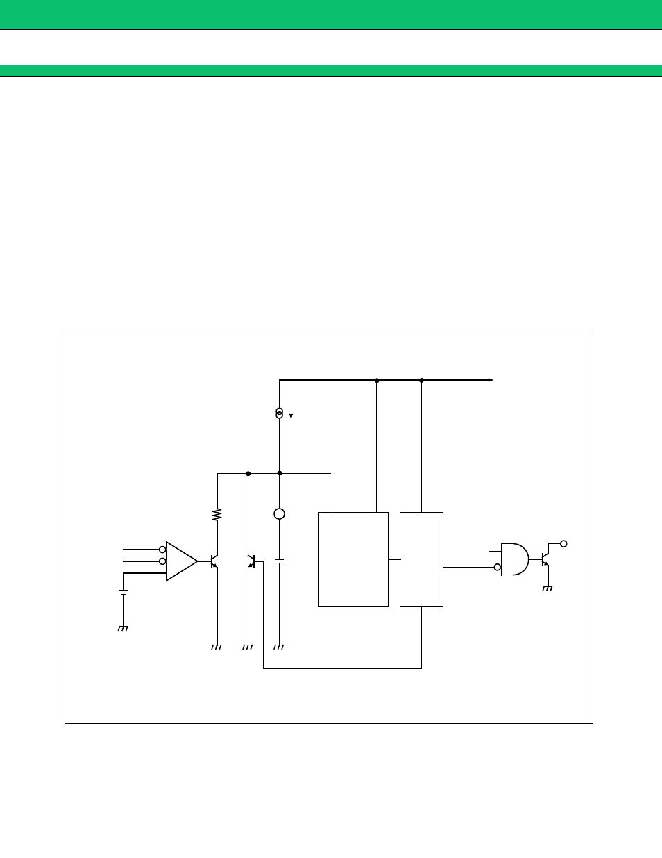
Fig. 5 Latch-Type Short-Circuit Protection Circuit
2.1 V
Low
input
voltage
protection
circuit
SR latch-type
circuit
1
µ
A
C
PE
-
-
+
OUT
2.5 V
15
Q
2
Q
1
Comparator 1
Comparator 2
S
R
PWM
comparator