Alarms, Power, Management interface – Foundry Networks AR SERIES User Manual
Page 15: Initial configuration, Larms, Ower, Anagement, Nterface, Nitial, Onfiguration
Installing and Configuring Rack-Mounted Systems
June 2004
© 2004 Foundry Networks, Inc.
2 - 5
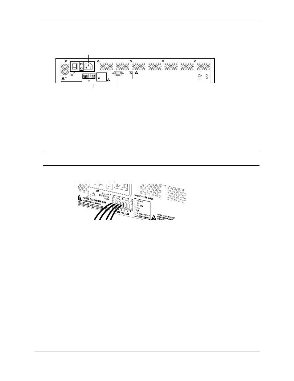
Alarms
Connect the stripped ends of two 18-22 AWG wires to alarm terminals 6 and 7 on the back-panel terminal block.
Power
Foundry systems operate on AC, single DC, and dual DC power. For AC power operation, connect the female end
of the supplied AC power cord to the AC power receptacle on the system back panel. Connect the male end of the
AC cord to a standard 110/120 VAC source. Refer to the figure above. Refer to the Installation Guide: Domestic
Products for information about dual AC power connection.
To operate with single-source DC power, connect the stripped ends of two 18-AWG wires to either the A or B
terminals on the terminal block. Make sure to connect the +48V lead to the appropriate RTN connector.
CAUTION:
To avoid equipment damage, make sure that the +48V lead is connected to the appropriate RTN
connector (either 1 or 3) on the terminal block.
To operate with dual-source DC power, connect the stripped ends of four 18-AWG wires to the both the A and B
terminals on the terminal block. Make sure to connect the +48V leads to the appropriate RTN connectors.
Management Interface
To access the command line interface (CLI) via the front-panel console port, connect a terminal or a workstation
running a terminal emulation software to the Foundry system. The software should be configured as follows:
•
9600 bps
•
8 data bits
•
1 stop bit
•
No parity
•
XON/XOFF flow control
To remotely access the system, configure the modem data port as specified above for terminal emulation
software. It is also possible to telnet to the Foundry system once an IP address is assigned to an Ethernet port.
Initial Configuration
Use the following commands to log in as the system administrator, choose a host name, change the password, set
the system time, and enter an Ethernet IP address.
SUMMARY
POWER
ESD
GND
1
2
3
4
5
6
7
SEE PRODUCT MANUAL
40 - 60V , 3.0A
CAUTION: TO PROTECT AGAINST
RISK OF ELECTRICAL SHOCK,
DISCONNECT BOTH AC POWER CORD
AND DC WIRING BEFORE SERVICING.
100-240V , 2.5A, 50-60Hz
AUX. PORT
FUSE: T3A, 250V SLOW BLOW
CAUTION: TO PROTECT
AGAINST RISK OF FIRE,
REPLACE WITH THE SAME TYPE
AND RATING OF FUSE ONLY.
5 - 7 in-lbs
0.57 - 0.79 N-m
TORQUE
1 - 48B RTN
2 - 48B
3 - 48A RTN
4 - 48A
5 -
6 - ALARM CONTACT
7 - ALARM COMMON
FOR CENTRALIZED DC POWER, INSTALL ONLY IN RESTRICTED ACCESS AREAS
Alarm Terminals
AC Receptacle