Pin assignment, Mb3878 – FUJITSU MB3878 User Manual
Page 2
MB3878
2
(Continued)
• Built-in current detector amplifier with wide in-phase input voltage range : 0 V to Vcc
• In standby mode, leave output voltage setting resistor open to prevent inefficient current loss
• Built-in standby current function : 0
µ
A (standard)
• Built-in soft-start function
• Built-in totem-pole output stage supporting P-channel MOS FETs devices
■
■
■
■
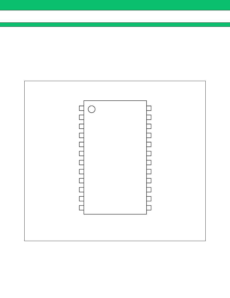
PIN ASSIGNMENT
(TOP VIEW)
(FPT-24P-M03)
1
2
3
4
5
6
7
8
9
10
11
12
−
INC2 :
OUTC2 :
+
INE2 :
−
INE2 :
FB2 :
VREF :
FB1 :
−
INE1 :
+
INE1 :
OUTC1 :
OUTD :
−
INC1 :
24
23
22
21
20
19
18
17
16
15
14
13
:
+
INC2
: GND
: CS
: VCC (O)
: OUT
: VH
: VCC
: RT
:
−
INE3
: FB3
: CTL
:
+
INC1