Ac adaptor voltage detection, Operation timing diagram, Mb3878 – FUJITSU MB3878 User Manual
Page 15
MB3878
15
■
■
■
■
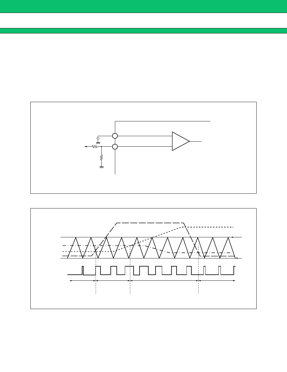
AC ADAPTOR VOLTAGE DETECTION
With an external resistor connected to the +INE2 terminal(pin 3), the IC enters the dynamically-controlled
charging mode to reduce the charge current to keep AC adaptor power constant when the partial potential point
A of the AC adaptor voltage (Vcc) becomes lower than the voltage at the -INE2 terminal.
AC adaptor detected voltage setting: Vth
Vth (V)
=
(R1
+
R2)
/
R2
×
−
INE2
−
INE2 setting voltage range : 1.176 V to 4.2 V (equivalent to 7 V to 25 V for Vcc)
■
■
■
■
OPERATION TIMING DIAGRAM
−
+
V
CC
R1
R2
+
INE2
−
INE2
A
4
3
2.5 V
1.5 V
Error Amp.1
Error Amp.3
Error Amp.2
FB1
FB3
FB2
OUT
Constant
voltage control
AC adaptor dynamically-
controlled charging
Constant current control
AC adaptor dynamically-
controlled charging