Furuno DS-30 User Manual
Page 29
3-10
3.3.6
Insulation of cables for transducer
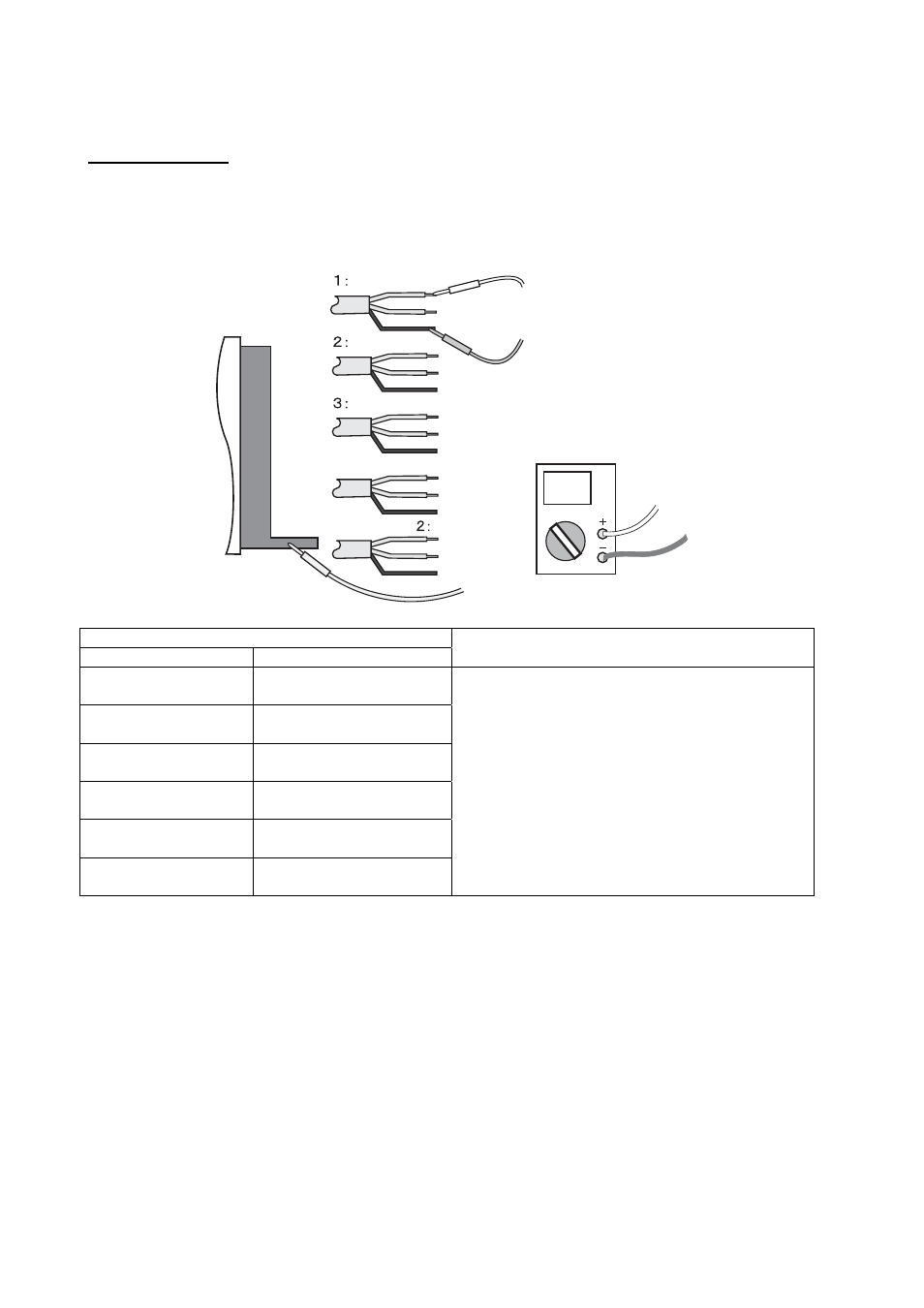
Insulation check
1. Remove all cores and shields of the transducer from the terminal board. All wires of the
transducer are open.
2. Set the multimeter to the maximum resistance range and measure the resistance
between each transducer line (TD1, TD2, TD3) and individual or common shield.
Multimeter
Red
Black
Cable of
transducer
TD
Black
TD
Red
TD
Green
Temperature Sensor 1 Yellow, White
Temperature Sensor
Blue, Grey
Red
Black
Red
Black
Measurement places
- polarity lead
- polarity lead
Insulation resistance value
Red wire of black
sheath
Shield in black sheath
Red wire of black
sheath
Common shield
Red wire of red
sheath
Shield in red sheath
Red wire of red
sheath
Common shield
Red wire of green
sheath
Shield in green sheath
Red wire of green
sheath
Common shield
Digital multimeter: More than 10M
Ω
Analog multimeter: Needle does not swing.
Note) If rating is not met a location, suspect faulty insulation. Replace a new one.