Functional description, Initial tool set up/ assembly, Specifications – Harbor Freight Tools 98733 User Manual
Page 7: Unpacking, Air supply
SKU 98733
For technical questions, please call 1-800-444-3353.
Page 7
FUNCTIONAL DESCRIPTION
Specifications
Working Air
Pressure Range
70-120 PSI
* (Depending on
nail length and wood density)
Air Inlet
1/4” -18 NPT
Nail Type
.113”-.131” diameter, 2-3/16” to
3-1/2” L, 21° Nails
Fastener Type
Plastic Collated Full Head Nails
Magazine
Capacity
60 Nails
Air Consumption
3 CFM @ 90 PSI
(Intermittent use)
12 CFM at 90 PSI
(Required for continuous use)
Safety Trigger
Single Sequential Actuation
* The pressure setting must not exceed the job
site regulations/restrictions.
INITIAL TOOL SET UP/
ASSEMBLY
Read the ENTIRE IMPORTANT
SAFETY INFORMATION
section at the beginning of this
manual including all text under
subheadings therein before set
up or use of this product.
Note: For additional information regarding
the parts listed in the following pages,
refer to the Assembly Diagram near
the end of this manual.
Unpacking
When unpacking, check to make sure
item is intact and undamaged. If any parts
are missing or broken, call Harbor Freight
Tools at the number shown throughout the
manual as soon as possible.
• This air tool may be shipped with a
protective plug covering the air inlet.
Remove this plug before set up.
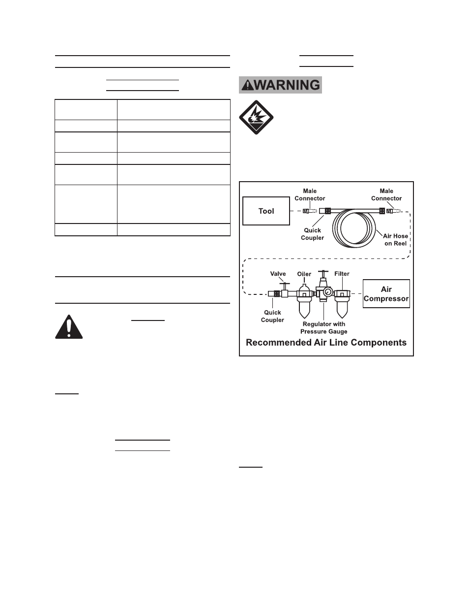
Air Supply
TO PREVENT
EXPLOSION:
Use only clean, dry, regulated,
compressed air to power this
tool. Do not use oxygen,
carbon dioxide, combustible
gases, or any other bottled
gas as a power source for this
tool.
1. Incorporate an in-line oiler, shut-off
valve, regulator with pressure gauge,
and filter for best service, as shown in
the diagram above.
An in-line shut-
off valve is an important safety
device because it controls the air
supply even if the air hose is rup-
tured.
Note: If an automatic oiler system is not
used, add a few drops of Pneumatic
Tool Oil to the airline connection be-
fore operation. Add a few more drops
after each hour of continual use.
2. Attach an air hose to the compres-
sor’s air outlet. Connect the air hose
to the air inlet of the tool. Other com-
Revised 09i; 09l