Wiring schematics, Legend, Envision low sill console installation manual – WaterFurnace Envision Low Sill User Manual
Page 19
19
ENVISION LOW SILL CONSOLE INSTALLATION MANUAL
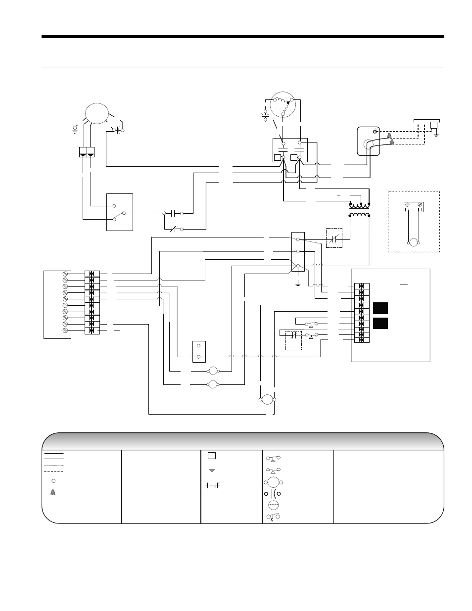
Wiring Schematics
CCM with Remote Thermostat - 208-230-265/60/1
Cap
Brn
Wht
Grn
PSC
Blower
Motor
Factory low voltage wiring
Legend
Wiring lug
Ground
Relay Contacts -
N.O., N.C.
Factory line voltage wiring
Quick connect terminal
Wire nut
Notes:
1. Switch Red and Blue wires for 208 volt operation.
2. Terminal C of the 24V PB is used as “L” output for
Brown wire 3 for Lockout.
3. When installed, 24VAC connection for remote
start/stop controller option.
L1
Factory low voltage wiring
Factory line voltage wiring
LP
HP
Unit
Power Supply
208-230/60/1 or
265-277/60/1
G
Handi - Box
Ground
Lug
H
L
CC
T2
T1
Compressor
C
R
S
Tan (33)
Red
Blk
Blue
L1
L2
High
Low
RV
RB
COMPRESSOR
CONTROL MODULE
TEST
PIN
HP
HP
CC
CG
LO
R
C
LP
LP
Y
HP
HP
CC
CG
LO
R
C
LP
LP
Y
Transformer
24V
Blue
230V
265V
Red
208V
Black
Yellow
Black/White
Black/White (1)
Red (2)
Black (6)
Black (7)
Blue (8)
Blue (9)
Violet (5)
Violet (4)
Yellow (10)
Orange (21)
Black (29)
Red (30)
NOTE 1
Black (22)
Black (25)
White (28)
Black (31)
Red (32)
Brown (26)
Black (27)
RB
4
2
5
C
RY
1
O
G
L
S
Te
rminal Board
X2
X1
W1
Brown
Brown (3)
NOTE 2
RSR
24 V Supply for Start/
Stop Signal
NOTE 3
3
1
FS
Green (00)
Green
Orange
Yellow
Black
Red
Pink
White
Not Used
97P827-01 6/24/11
PB
1
2
3
RSR
4
5
Blower Switch
CC
Legend
CC - Compressor Contactor
HP - High Pressure Switch
LP - Low Pressure Switch
RV - Reversing Valve Coil
ST - Entering Air Temperature Sensor
RB - Blower Relay
DT - Damper Terminal Block
PB - Power Block
FS - Freeze Sensing Device
RSR – Remote Start/Stop Relay
Temperature Switch
Switch - High Pressure
Switch - Low Pressure
Relay coil
Capacitor
Thermistor
HP
LP
T
Pink
Violet (5)
Violet (4)
NOTE 3
1
3
PB-2
1
2
Brown
Red
Black
Yellow
Yellow (10)
Orange
Green