Leslie Controls GP Pressure reducing valve User Manual
Page 4
Page 4
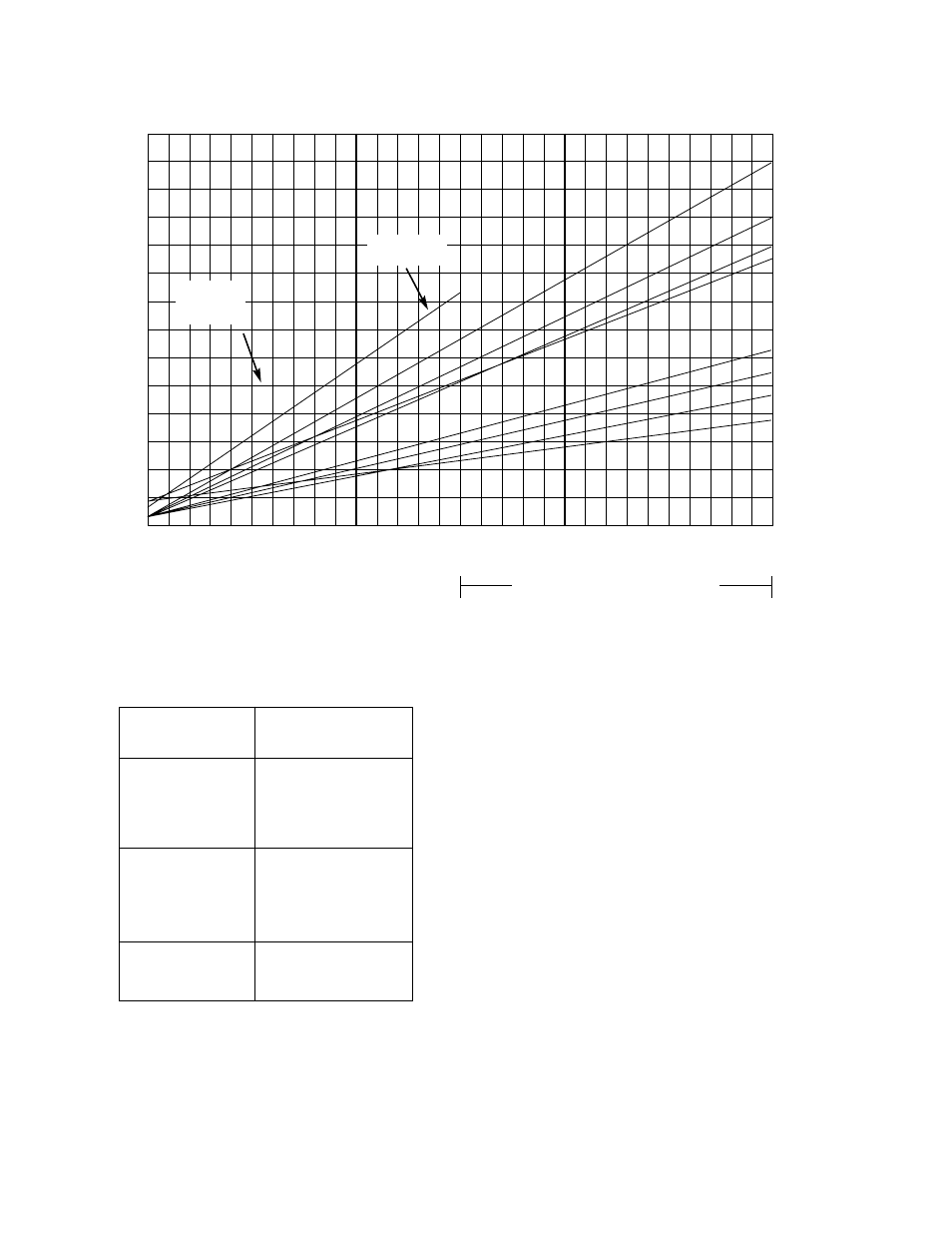
DIAPHRAGM PRESSURE ABOVE REDUCED PRESSURE
70
65
60
55
50
45
40
35
30
25
20
15
10
5
0
GPS-1T (S)
GPK-4T (S)
limit 25 psi
4” GPS-1
4” GPK only
100
200
300
400
500
600
PRESSURE DROP PSI (INLET PRESSURE MINUS OUTLET PRESSURE)
Classes GPHS & GPHS-1 only
4“ GPHS and
GPHS-1 only
1-1/2” and 2”
3”
1”
2-1/2””
3/4”
1/2”
MAX. INLET*
CLASS
& MAX.
∆
P
GPK
250
GPB
300
GPS
300
GPS-1
300
GPHS
600
GPHS-1
600
GPAK
400
GPAS-1
400
*Subject to valve body limitations.
The above curves indicate the loading pressures above the
outlet pressure require for each size class GPK, GPAK,
GPB, GPS, GPHS, GPS-1, GPHS-1, and variants for all pres-
sure differentials across the valves.
EXAMPLE: If a 3” GPB reducing valve is required to reduce
steam from 300 psig to 20 psig, 44 psig air loading is
required. This is determined as follows: Enter the chart at
280 psi pressure drop and read up to the 3” size. Read
across to 24 psi, which must be added to the outlet pressure
to determine the required loading pressure.
NOTE: Maximum diaphragm joint pressure is 300 psig.
Loading pressure (reduced pressure plus diaphragm pres-
sure above reduced pressure must not exceed 300 psig.
SECTION II — OPERATION (CON’T)