C.2 trigger devices, C.2.1 hall effect sensors – Haltech IG5 User Manual
Page 74
70
FigureC.2
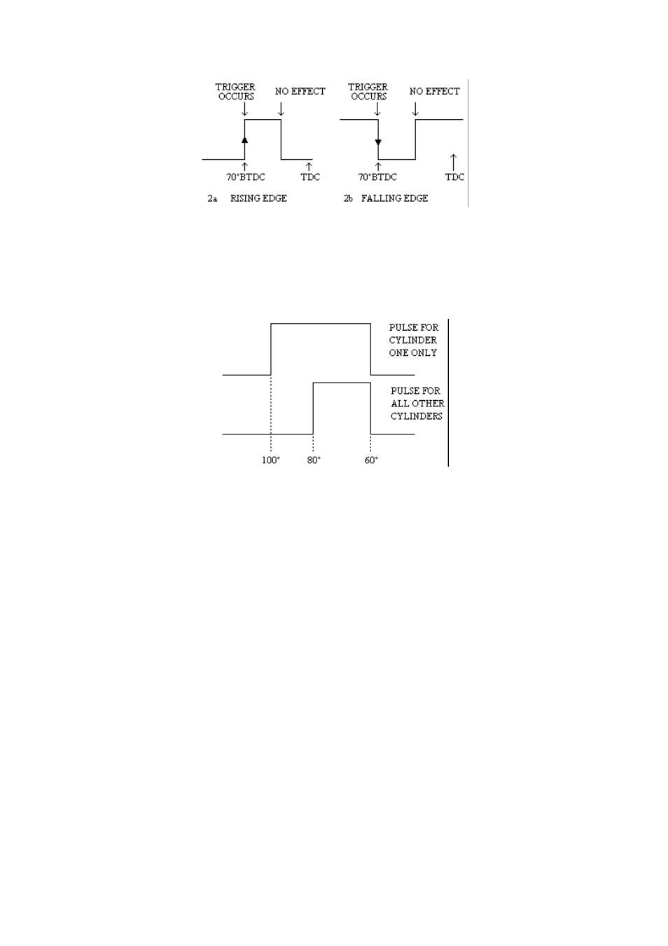
In the example shown in figure C.3 the pulse width for cylinder one is different to the pulses
of all the other cylinders. If rising edges were used as the trigger input there would be a
variation of 20° between the trigger timing for cylinder one and all other cylinders. Falling
edge would need to be set in this case and the trigger degrees set to 60° BTDC.
Figure C.3
C.2 Trigger Devices
C.2.1 Hall Effect Sensors
Hall Effect sensors are often used in original equipment and may be directly connected to the
IG5. These devices require three connections:
Power (normally +12v)
Ground
Trigger output
Many distributors used in electronic ignition systems are fitted with mechanical and/or
vacuum advance mechanisms. These mechanisms must be locked so that the IG5 receives a
an input trigger signal with fixed relationship to crankshaft position. If you elect to rotate the
distributor housing when setting the timing relationship of the trigger signal to the crankshaft
position (the trigger angle) , read Appendix D, Rotor Phasing, first.
Haltech Hall Effect Sensors
The Haltech hall effect sensor is a two channel device that can be used to trigger the Haltech
range of ECU’s in a wide range of applications.