Industrial Injection LBZ Dual CP3 User Manual
Page 3
Dual Fueler CP3 Pump Kit for LBZ
Dual Fueler CP3 Pump Kit for LBZ
6
3
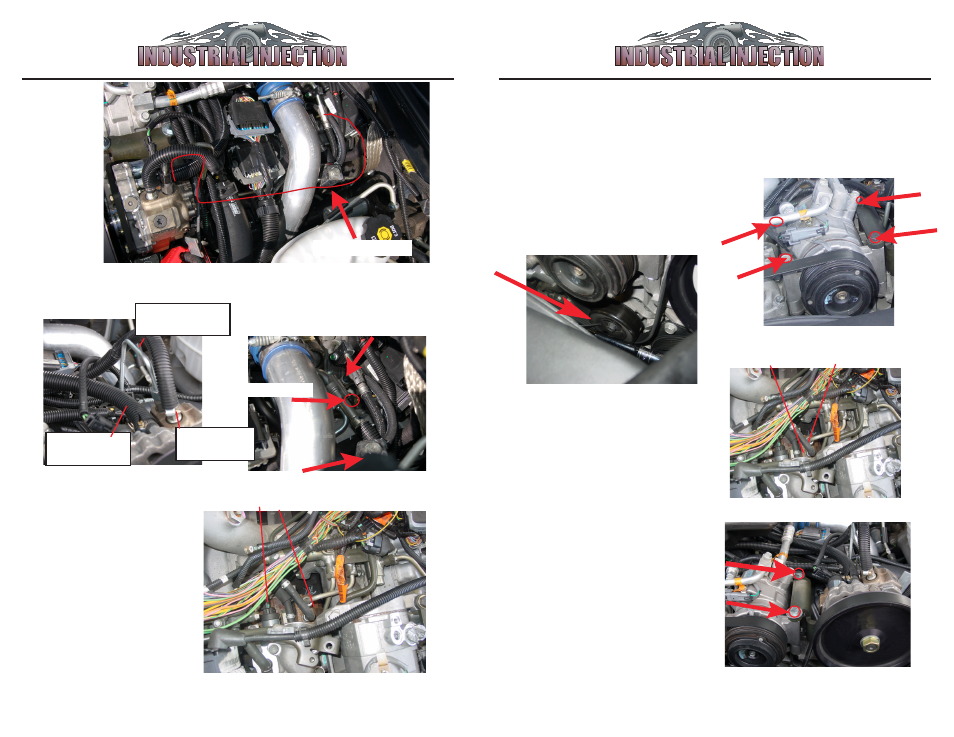
1. Remove belt and Install
#5
Idler Pully
in existing threaded
hole on engine bracket as shown
below. Torque to 27 lb ft.
2. Remove
4 A/C Bolts
as shown
and set
A/C compressor
to the
left of the engine to access fuel
line below.
Fig. 1
Fig. 2
First: Install “Dual Fueler”
bracket and pully if not assembled
on pump. Refer to Appendix B on
page 8.
3. Locate Stock CP3 Pump
C
and
locate stock return line
D
from Stock
CP3 Pump. Cut rubber hose and insert
#3
5/16”x5/16”x5/16” ‘T’ connector.
Use
#11
hose clamps to secure.
C
D
4. Place A/C Compressor back into
original position. Place
#6, (Dual
Fueler Assembly bracket with pump)
on top of the Right A/C Compressor
bolt holes and use
#12 bolts
to attach
Dual Fueler Bracket Assembly to A/
C Compressor, torque 37 lb ft. Save
1 original A/C bolt for the next step.
13. Connect fuel return line from
#19a fuel relief fitting
to
fuel return
#19b
. Install
#9 rubber cap
on fuel
rail open fitting.
#19 flow relief
fuel return #19b
#9 rubber cap
15. Locate Stock CP3
Pump
C
, and locate
electronic control wire
harness
E
. Unplug wire
Harness
E
.
C
E
16. Plug Wire Harness
E
into
#13 control module
plug
, then plug other end
of
#13
control module
plug back into Stock CP3
Pump
C
.
12. Attach lines by part
number as shown below:
14. Install Module M back to its
original position.
#4
: High Pres-
sure Line
#3
: Return
Line
#2
: Inlet Fuel
Line
#19 flow relief