Pply the, Ads to a, Positioning the lifter on the load – Wood’s Powr-Grip MT10FS10TDC User Manual
Page 14: Sealing the pads against the load, Reading the vacuum gauge
Rev 30.0/5-14
12
MT-FS10TDC: #35091
T
O
A
PPLY THE
P
ADS TO A
L
OAD
Positioning the Lifter on the Load
Make certain that the contact surfaces of the load and all vacuum pads are free of any
contaminates that could prevent the pads from sealing against the load (see MAINTENANCE:
V
ACUUM
P
AD
M
AINTENANCE
).
The lifter is designed to automatically carry the load in an upright orientation. Center the pad
frame from left to right on the load. Determine which will be the top edge of the load while
lifting, and position the long row of vacuum pads near that edge.
7
This position will maximize
stability while lifting the load. Make sure that all activated pads will fit entirely on the load’s
contact surface (see SPECIFICATIONS: Maximum Pad Spread) and that they will be loaded
evenly while lifting (see SPECIFICATIONS: Per-Pad Load Capacity).
Sealing the Pads against the Load
Pull the vacuum package valve handle
outward until it latches securely in the
“APPLY” position (power on), as shown,
to energize the vacuum pump. The red
low vacuum warning light also turns on
and remains illuminated until the lifter
attains sufficient vacuum to lift the
maximum load weight (see Load
Capacity and the Warning Light to follow).
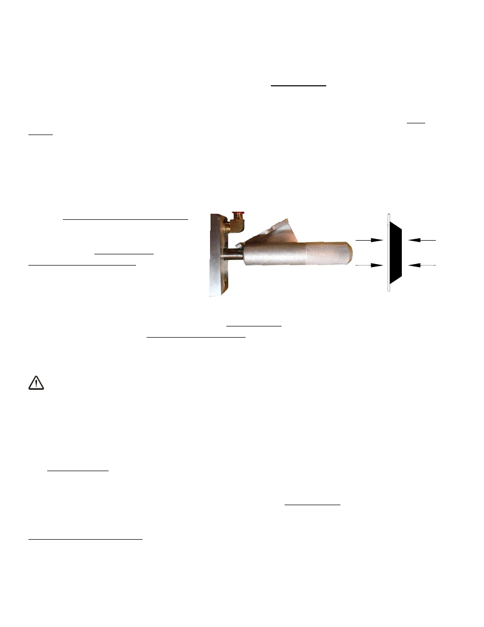
Apply the lifter to the load so that all activated vacuum pads are touching the contact surface.
Then move the slide on the pad frame control valve to the “APPLY” position, and press the lifter
onto the load until the pads seal against the contact surface.
8
Both the vacuum package valve
handle and the pad frame control valve must remain in the “APPLY” position throughout the
entire lift.
WARNING: Keep pad frame control valve and vacuum package valve handle
latched securely in “APPLY” position throughout lift.
Note: If a vacuum pad has been lying against a hard object (as during shipping), it may be
slightly distorted. Although initially it may be difficult to apply the pad to a load, this condition
should correct itself with continued use.
Reading the Vacuum Gauge
The vacuum gauge indicates the current vacuum level in the lifter’s vacuum system. The
green
range indicates vacuum levels sufficient for lifting the maximum load weight, whereas the
red
range indicates vacuum levels that are
not
sufficient for lifting the maximum load weight. The
gauge needle should show a sudden surge in vacuum as the vacuum pads seal against the load.
If it takes more than 5 seconds for the vacuum level to reach 5" Hg [-17 kPa], press on any
activated pad that has not yet sealed.
7
This is the
only row of pads on models MT4FS10TAIR and MT6FS10TAIR.
8
To conserve battery energy and reduce the time required to apply the pads to a load, do not place the vacuum package valve
handle and the pad frame control valve in the “APPLY” position at the same time unless the vacuum pads are contacting the load.
VACUUM PACKAGE VALVE HANDLE / TO APPLY