Hange the, Rame, Onfiguration – Wood’s Powr-Grip MR1611LDC User Manual
Page 10
Rev 30.0/5-13
8
MR1611LDC: #35050
T
O
C
HANGE THE
P
AD
F
RAME
C
ONFIGURATION
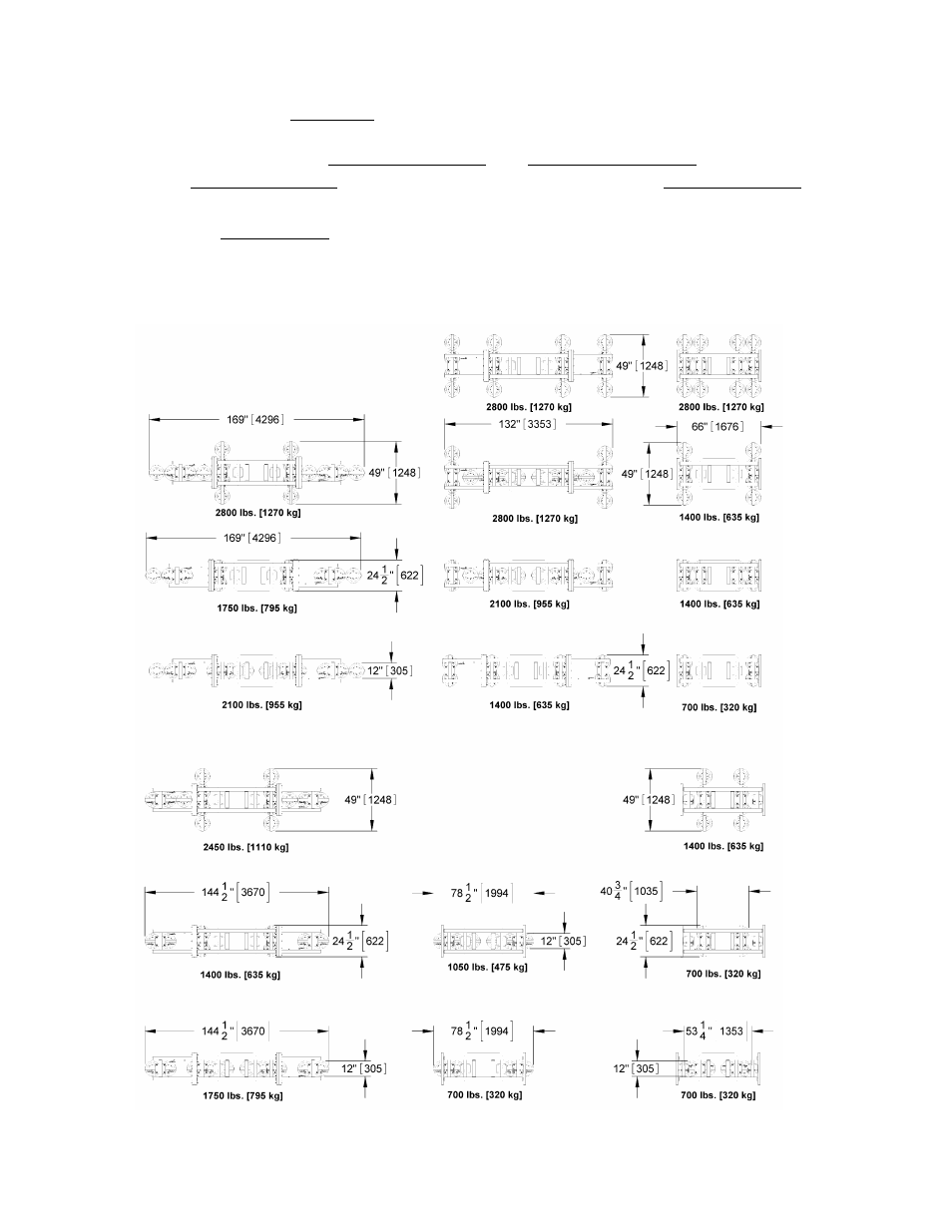
This lifter offers a variety of pad frame configurations to accommodate different load dimensions
and weights (see illustrations on following page). Configurations are created by installing or
removing the pad frame’s outer, removable sections and removable pad arms, and/or by rotating
the pad frame’s rotating pad arms. Some configurations also require the lift bar extension to be
installed (see To Install the Lift Bar Extension to follow).
Always arrange the vacuum pads in a symmetrical configuration, in both horizontal and vertical
dimensions. After changing the pad frame configuration, make sure all vacuum hoses are secure
and routed to avoid being pinched, snagged, abraded or otherwise damaged while the lifter is in
operation. Also be sure to verify that all pads are connected and functioning correctly.
Pad Spread and Maximum Load Capacity