Assembly, Et up the, Ifter – Wood’s Powr-Grip MRTALPCH611LDC User Manual
Page 9
Rev 8.0/6-13
7
MRTALPCH6-DC: #35054
ASSEMBLY
T
O
S
ET UP THE
L
IFTER
1) Open the shipping container and remove all materials for restraining or protecting the vacuum
lifter. Save the container for use whenever the lifter is transported.
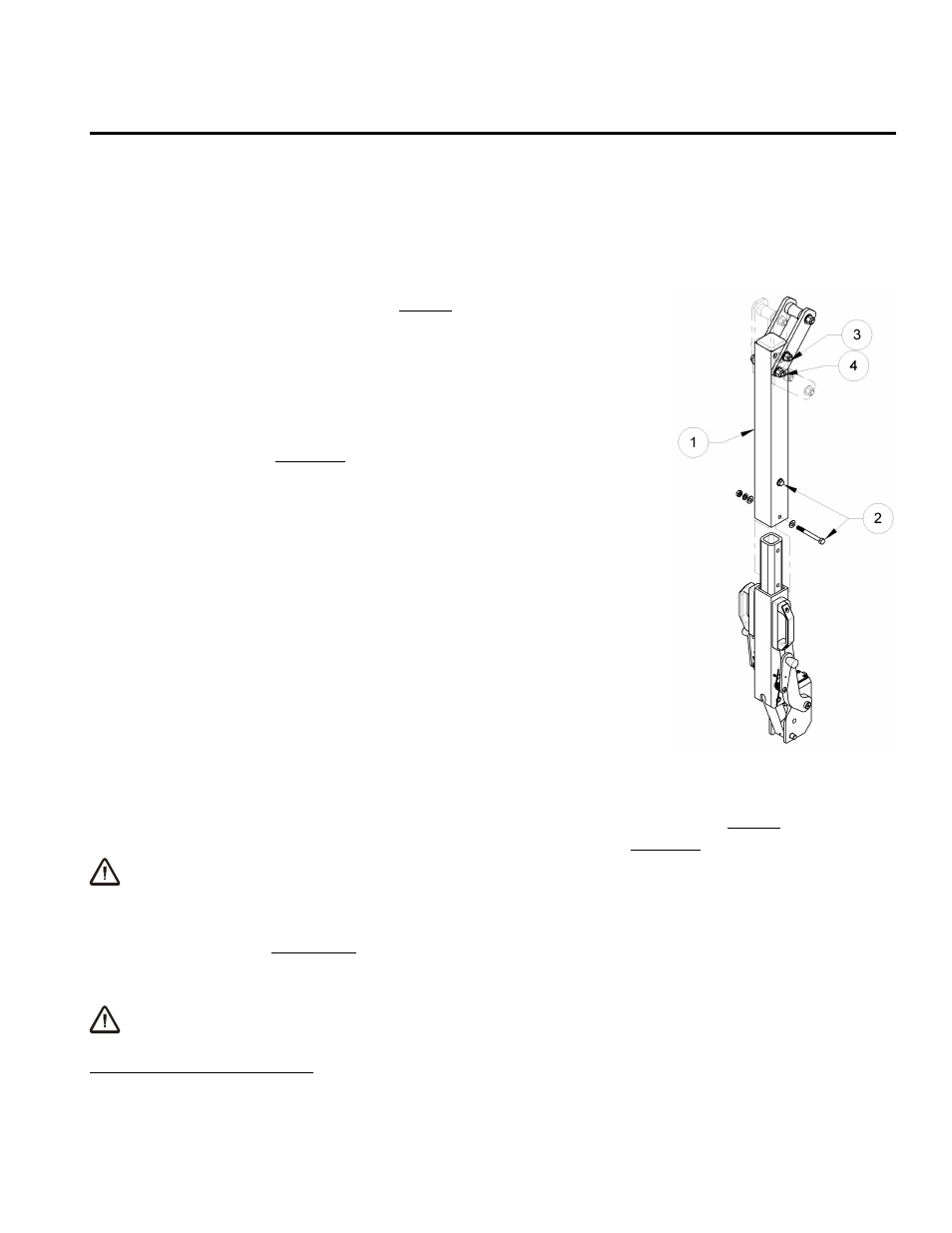
2) If necessary, assemble the lifter's lift bar as follows: One
segment of the lift bar can be removed, to reduce overall lifter
dimensions for shipping. If so, orient the removable segment
(1) as shown in the illustration, and slide it over the other
segment until the bolt holes align. Reinstall the bolts and all
associated hardware (2); then tighten both bolts securely.
3) Position the lifter's lift spool as follows: The adjustable lift spool
assembly provides 3 different lift points (see illustration), in
order to optimize the lifter's hang angle and/or its overall height
for the intended use.
3
To change the lift spool position, remove
the retaining bolt (3) and, if necessary, loosen the pivot bolt (4).
Next pivot the lift spool assembly until the bolt holes align for the
desired spool position. Then reinstall the retaining bolt and all
associated hardware. Tighten both bolts securely.
4) Suspend the lifter from a crane as follows: Select hoisting
equipment (crane and hoist, when applicable) rated to carry the
maximum load weight plus the lifter weight (see
SPECIFICATIONS: Maximum Load Capacity and Lifter Weight).
Note: Any application of the lifter must conform to all statutory
or regulatory standards that relate to the hoisting equipment when used in its geographical
location (eg, relevant OSHA standards in the USA).
Disengage the tilt latch (see OPERATION: T
O
T
ILT THE
L
OAD
) and raise the lift bar to a vertical
orientation. Then attach the hoisting equipment hook to the lift spool.
WARNING: Hoisting equipment hook must be fitted with restraining latch to
prevent lift spool from slipping off under any circumstances.
Note: Some hoisting equipment hooks could interfere with an upright load that extends
beyond the lifter's pad frame. If the load would contact the hook during lifter operation, the
operator must prevent this by attaching a sling (or other rigging that does not interfere with
the load) between the hook and the lift spool.
WARNING: Any sling used must be rated to carry maximum load weight plus
lifter weight.
3
When the pad frame is used in the vertical orientation (see illustration in OPERATING FEATURES), placing the lift spool in the
lowest position creates interference with the pad frame extension. To avoid this problem, place the lift spool in one of the other
two positions or remove the pad frame extensions (see T
O
C
HANGE THE
P
AD
F
RAME
C
ONFIGURATION
to follow).