Caution – Goulds Pumps 3409 - IOM User Manual
Page 43
7.
Assemble casing rings (127). (See Adjustable Wear
Ring Section, if required.)
8.
Start heating bearings (168 & 410) so that they will be
ready when called for in step 11. Use dry heat from
induction heat lamps or electric furnace, or a 10-15%
soluble oil and water solution.
$
CAUTION
Do not exceed 275° F.
$
CAUTION
These are precision, high quality bearings. Exercise care
at all times to keep them clean and free of foreign matter.
9.
Press inboard bearing isolators (333A) in each bearing
cover. Install gaskets (360) on each bearing cover.
10. Slide bearing covers (109 & 119) on the shaft. Install snap
rings (276). Install thrust washer (535) on the outboard
end.
NOTE: For ease of assembly and protection of rubber
parts while sliding rubber parts onto shaft, cover O-ring
groove, keyways, and threads with electrical tape.
NOTE: Inboard bearing cover (119) is approximately 1/4
inch less in width than the outboard bearing cover (109).
This is the only dimensional difference.
11. Press heated bearing (168 & 410) on shaft against snap
ring or thrust washer. Install locknut (136) and lockwasher
(382) on outboard end. Make certain locknut is secured
and then bend over tab on lockwasher.
PUMPS WITH GREASE LUBRICATION
12. Cool bearings at room temperature and coat with 2 or 3
ounces of a recommended grease.
PUMPS WITH OILLUBRICATION
Refer to Oil Lubricated Bearings Section for installation of
oil lubricated parts.
13. Press outboard bearing isolator (332A) in coupling end
bearing housing.
14. Slide bearing housings (134) onto shaft (122) over
bearings (168 & 410).
15. Assemble bearing cover to bearing housing with two cap
screws (371C).
16. Replace pump coupling half and key (400).
17. Assemble rotating element in lower half casing (100).
Correctly locate casing ring pins (445A) in casing main
joint slot.
NOTE: Sliding inboard bearing housing toward coupling
prior to assembling rotating element in casing will ease
assembly.
18. Bolt outboard bearing housing in place. Be sure that both
housings are seated properly in lower half casing.
19. Bolt inboard bearing housing in place.
3409 IOM 11/04
43
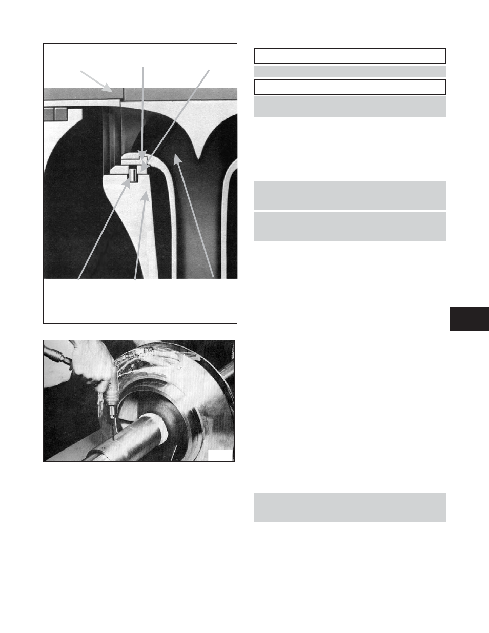
Fig. 19
(126)
SLEEVE
(142)
IMPELLER RING
(127)
CASING RING
LOCKING PIN
(445A)
CASING
(100)
IMPELLER
(101)
Fig.18
6