Assembly (pump with packing), Caution – Goulds Pumps 3409 - IOM User Manual
Page 42
8.
Pull coupling half and key (400) off shaft (122).
NOTE: A spare rotating element can be installed at
this point.
9.
Remove cap screws (371C) from bearing covers (109
& 119).
10. Remove bearing housings (134), locknut (136), and
lockwasher (382). Mount bearing puller and remove
bearings (168 & 410). Remove thrust washer (535)
and snap rings (276).
NOTE: Locknut, lockwasher, and thrust washer are
not used on inboard bearing.
$
CAUTION
Do not reuse ball bearings.
11. Remove bearing covers (109 & 119) and push bearing
isolators out of bearing covers and coupling end
bearing housing (332A & 333A).
12. Remove casing rings (127) from impeller (101).
13. Remove set screw (222B) from shaft nuts. Remove
shaft nuts (124), O-rings (497), sleeves (126), sleeve
gaskets (428), and impeller (101).
NOTE: Apply heat uniformly to the shaft sleeve to
loosen the sealant between the shaft and sleeve. DO
NOT HEAT ABOVE 275° F. To further assist in
removing the sleeves, hold the shaft vertically and tap
it on a block of wood. The impeller weight should
force both the impeller and sleeve from the shaft.
14. See Adjustable Wear Rings Section if pump is
equipped with adjustable rings.
NOTE: For impellers with replaceable rings —
remove the rings (142) by cutting the rings with a cold
chisel. (See Fig. 18)
ASSEMBLY (PUMP WITH PACKING)
!
Packed stuffing boxes are not allowed in an ATEX
classified environment.
All bearings, O-rings, seals, gaskets, impeller rings, and casing
wear rings should be replaced with new parts during assembly.
All reusable parts should be cleaned of all foreign matter before
reassembling. The main casing joint gasket should be made
using the lower half as a template. Lay the gasket material on
the casing joint and mark it by pressing it against the edges of
the casing. Trim the gasket so that it is flush with the inside
edges of the casing.
NOTE: Precut casing gaskets (351D & 351S) can be
ordered to minimize the amount of trimming.
1.
Place impeller key (178) in shaft (122).
2.
Check the impeller (101) and casing (100) to
determine the correct impeller rotation (See
Fig. 15) and locate the impeller on the shaft per
dimension “A”. (See Fig. 16)
NOTE: For impellers with replaceable rings, heat each
new ring (142) and slide it onto the impeller. Hold rings
against the impeller shoulder until they cool. (See Fig. 19
3.
Place both shaft sleeve keys (401) on shaft (122).
4.
Slide sleeve gaskets (428) onto shaft and against hubs
of impeller.
5.
Slide sleeves (126) onto shaft.
6.
Place the sleeve O-ring (497) onto the shaft, into the
sleeve counterbore. Verify that Dimension “A”
(Fig. 16) is maintained, then using a pin spanner wrench
and hammer, securely tighten the shaft sleeve nuts
(124). Then, drill a shallow recess in the shaft through
the set screw hole in each of the shaft sleeve nuts. Lock
each shaft sleeve nut in position with cup point set
screws (222B). (See Fig. 19) A low strength sealant,
such as Loctite 271, can be used to retain set screws.
42
3409 IOM 11/04
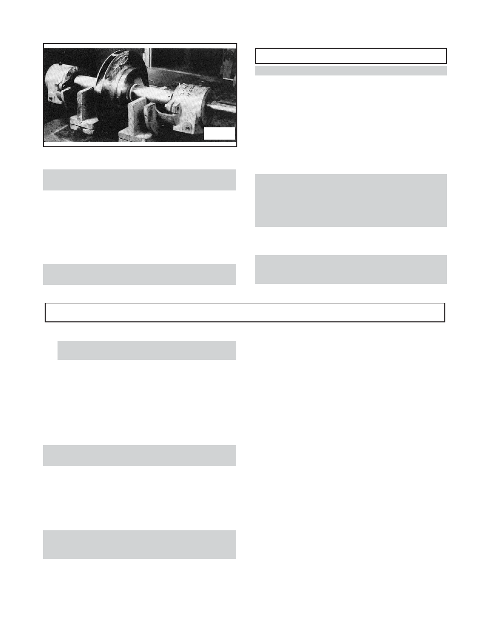
Fig. 17