Operational adjustment – Hawk Industries Spinner Manual 550 HYDRAULIC Serial Numbers 206 to 591 User Manual
Page 15
15
Operation
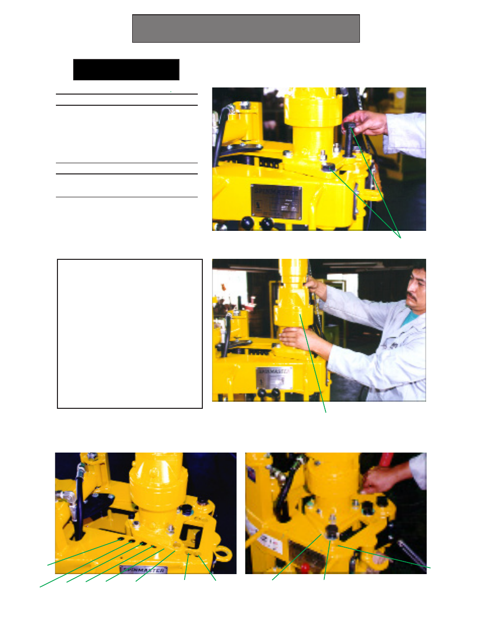
Operational Adjustment
1. Remove both Adjust Pins (AB)
2. Slide Drive System (DS) for-
ward or back to allign with the
desired pipe size adjustment
holes. See prior page(diagram)
or this page (photos) for correct
adjustment location.
3. Replace Adjust Pins (AB). New
Quick Release Pins look differ-
ent than shown on photo.
Adjust Pipe Size
AB
DS
Note
If the drive rollers are touching each
other while gripped on pipe, slip-
ping may occur. This is caused by
chain stretch (pin wear). To remedy
this problem, adjust the Spinmaster
to the next smallest setting. If this
smaller setting causes the Spin-
master to thrust itself from the pipe
while spinning, replace the chain.
See Changing the Chain pg.23.
950 Spinmaster
550 Spinmaster
2 7/8"
9 1/2"
8"
7" 6" 5" 4 1/2"-5"
3 1/2"-4" 2 7/8"
4 1/2"-5 1/2"
3 1/2"-4"