DataComm 70-0050 Home Command Center II User Manual
Instruction / installation sheet
2/25/08 Rev. 1
Instruction / Installation Sheet
DataComm Electronics Home Command Center II 70-0050
Step 1 Installation of Back Panel
Place plate with telephone 110 IDC on wall location and trace openings
for cut outs on wall. Remove plate and make cut outs for cables. Pull
telephone and television cables through cut outs in the wall.
Pull cables through back of plate 70-0050 module plate and secure plate
to wall using mounting holes provided on the plate.
Step 2 Telephone
Install the wire from the telephone demarcation point to the 110 IDC
marked from Telco.
Install the twisted pair cables from each location in the house to the
remaining 110 IDC connectors. Match the color-coding of the wires to the
colors on the 110 IDC connectors. Incoming phone service can be tested
using the test port.
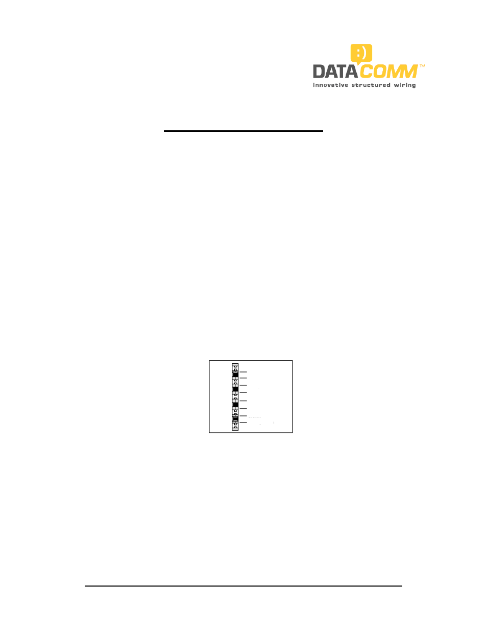
All cables should be punched down, using an industry standard punch-
down tool, to the 110 IDC connectors following the T568A wiring
configuration as shown below.
Line 1 is Blue, Line 2 is Orange, Line 3 is Green and Line 4 is Brown.
White / Blue
Blue
White / Orange
Orange
White / Green
Green
White / Brown
Brown
Step 3 Video
Attach a male F-connector onto the cable TV service or satellite service
incoming cable. Screw the incoming cable with F-connector to the
connector marked input.
Using F-connectors, terminate all coaxial leads that have been pulled
through the cut outs in the wall to the remaining connectors on the
splitter.
Secure the cover of the 70-0050 module to the back panel and tighten
screws located at the bottom of the back plate of the module.
INSTRUCTIONS ARE CONTINUED ON THE BACK SIDE OF THIS PAGE
DataComm Electronics, Inc.
6349 Peachtree Street
Norcross, GA 30071-1725
888.223.7977
770.662.8205
www.datacommelectronics.com