Proface APL3000B - Node Box PC User Manual
Page 60
Chapter 3 PS-A Monitoring Features
3-7
External Output Signal
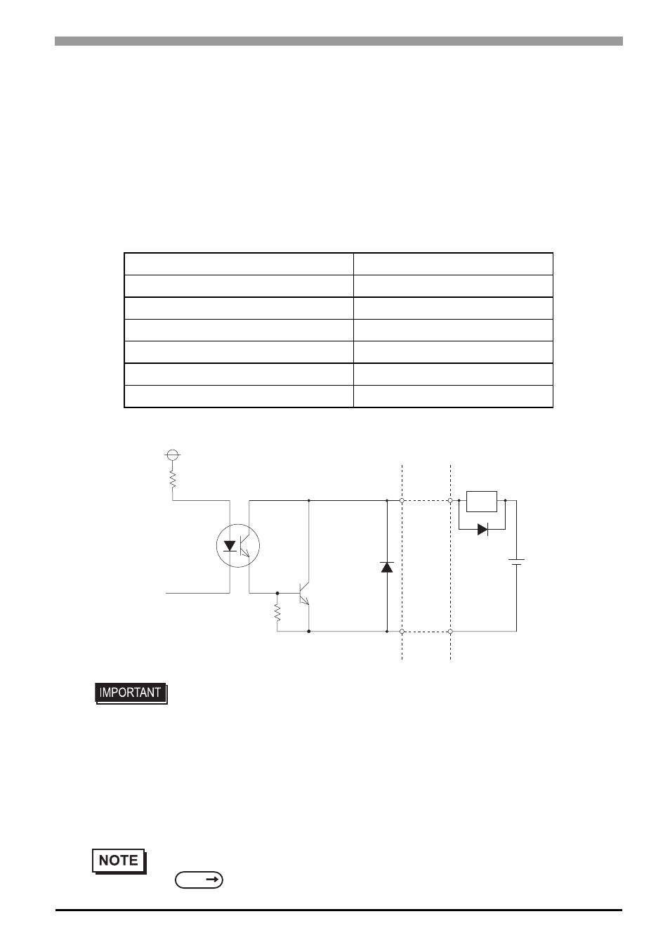
The PS-A’s RAS interface connector uses the following output signals.
•
General-Purpose Output (DOUT 4 bits)
This general purpose digital output signal provides system condition information to external devices.
The System Monitor property of the control panel or the API-DLL is used by applications to control this signal.
The above mentioned general purpose digital output signals provide system condition information to
external devices.
The System Monitor property can be used to enable or disable any of these output signals.
Rated Voltage
DC12V to 24V
Maximum Load Current
120mA/point
Out Voltage Drop
1.5V or less( at 100mA load current )
Output Points
4 points
Isolation Method
Photocoupler Isolation
Dielectric Strength Voltage
500V or more
External Power Supply
DC12V / 200mA, DC5V/100mA
• Be sure to operate the unit within its maximum load current. If the maximum load
current exceeds this range, a malfunction or PS-A damage may occur.
• Design your electrical system by adding the load current and voltage values to the
terminal voltage. If load current value used is large, the voltage drop of 1.5V or less
will occur between the terminals.
• When connecting an induction load, be sure to connect the above drawing’s
protection diode (*1).
•
For connection pin location details,
+5V
R
PC357
4.7kΩ
SSTA06
Cable
*
1
DC12V
to
24V
DOUT2(+) pin # 8
DOUT0(+) pin # 10
DOUT1(+) pin # 20
DOUT3(+) pin # 22
DOUT2(-)
pin # 7
DOUT0(-)
pin # 9
DOUT1(-)
pin # 19
DOUT3(-)
pin # 21
( Interface Circuit )
Load
SEE
PS-3710A/PS-3711A Series Hardware Manual 2 Specifications