4 main memory installation, 5 expansion board installation, 4 main memory installation -16 – Proface APL3000B - Node Box PC User Manual
Page 107: 5 expansion board installation -16
PL3000 Series Hardware Manual
5-16
5.3.4
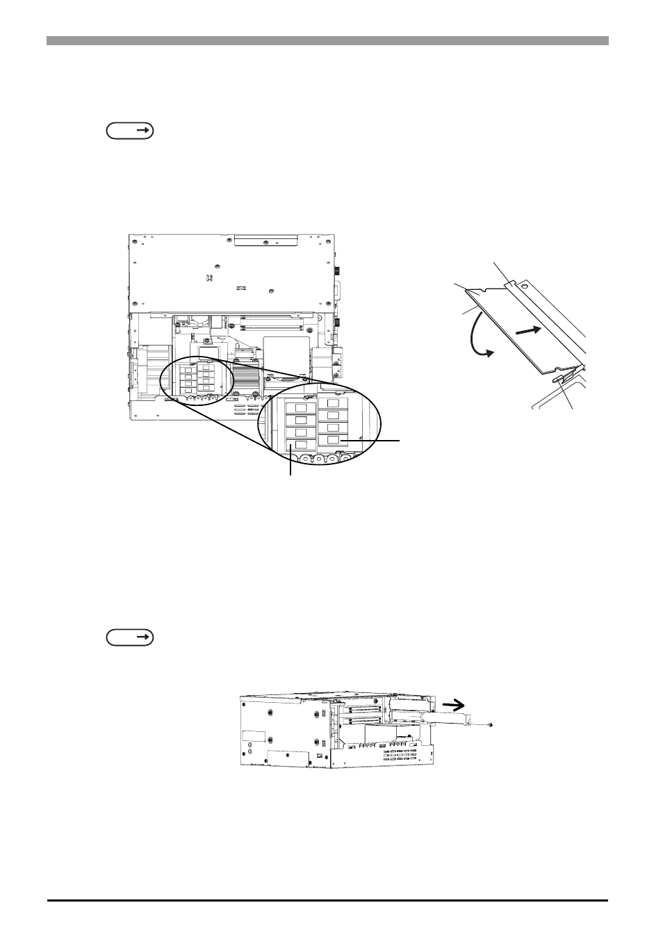
Main Memory Installation
(1)
Remove the PL unit’s expansion slot cover.
(2)
The DIM modules are installed in the DIM sockets as shown in the figure below. Angle the module
down slightly, insert it completely into the connector, and then push it in until the stopper snaps into
place.
5.3.5
Expansion Board Installation
(1)
Remove the PL unit’s expansion slot cover.
(2)
Remove the screw from the blank panel of the expansion slot and detach the blank panel.
SEE
5.3.3 Removal of Expansion Slot Cover (page 5-15)
SEE
5.3.3 Removal of Expansion Slot Cover (page 5-15)
Connector
Main Memory
Stopper
(2)
(1)
DIM Socket 1
DIM Socket 2