3 end trucks – Harrington Hoists and Cranes HPC 500 End Truck User Manual
Page 14
14
3.3
End Trucks
3.3.1
Read through all steps completely before proceeding with installation.
3.3.2
All operations associated with the assembly and installation of the end trucks
and/or the crane system should be performed under the supervision of a Qualified Person (see Section
5 for the definition of Qualified Person).
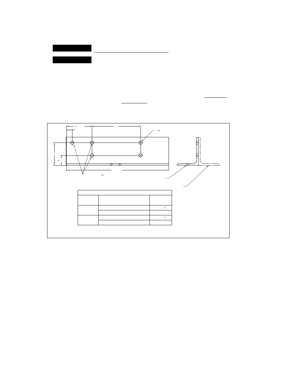
3.3.3
End Bracket Preparation
– Prior to assembling the end trucks prepare the four (4) end brackets (2 end
brackets per end truck) as follows:
Measure
“T” for the runway that the end trucks will be installed on. For Underhung “T” is the flange
width of the runway beam; for Top Running
“T” is the width of the rail head or square bar
(whichever is being used).
Drill tw
o 9/16” diameter holes in each of the four (4) end brackets in accordance with Figure 3-5.
4 REF.
1
3
4
REF.
1 REF.
4
1
2
REF.
17 REF.
D
EXISTING Ø
9
16
HOLES
BRACKET "A" (AS
SHOWN)
BRACKET "B" (OPPOSITE HAND)
Ø
9
16
- 2 HOLES (DRILL THESE HOLES)
FORMULA
FOR "D"
D = T + 5
D = T + 4
3
4
D = T + 5
D = T + 4
3
4
BEAM WITH FLAT FLANGE
BEAM WITH TAPERED FLANGE
RECTANGULAR SHAPED RAIL
ASCE RAIL
UNDERHUNG
TOP
RUNNING
RUNNING
SURFACE
CRANE
CONFIG.
"D" DIMENSION (INCHES)
T = I-BEAM FLANGE OR RAIL HEAD
- WIDTH MEASUREMENT
Figure 3-5 End Bracket Holes
3.3.4
Wheel Assembly Installation
– Install the Wheel Assemblies to the end trucks as shown in Figure 3-6.
Make sure you locate the Wheel Assemblies properly for your application (Underhung or Top Running)
as shown in Figure 3-7. To prevent the axle from turning when tightening the hex nut, use an air-
powered nut driver. Then, finalize the installation by applying torque to each wheel’s hex nut as follows.
75 ft-lb for HPC505
200 ft-lb for HPC510 and HPC520