Harrington Hoists and Cranes HPC 500 End Truck User Manual
Page 12
12
Table 3-1 Bridge Beams for a MANUAL or E
LECTRIC
H
OIST
on an HPC500 Crane
Important information about this table:
Includes 15% Allowance for Electric Hoist Load Factor.
Based on Harrington’s manual chain hoist product.
For spans greater than 10 ft., braces between end truck & bridge beam should be used.
Cap.
(Tons)
Maximum Allowable Span (ft)
10
15
20
24
½
S8 X 18.4
S8 X 18.4
S8 X 18.4
S10 X 25.4
1
S8 X 18.4
S8 X 18.4
S10 X 25.4
S10 X 25.4
2
S10 X 25.4
S10 X 25.4
S12 X 31.8
S12 X 31.8
C8 X 11.5
3.2.4
Fabrication
– Preparation of the Bridge Beam for assembly with the HPC500 End Trucks requires that
holes be drilled in the beam as follows. Refer to Table 2-1 and Figure 2-1 for definitions of all letter
variables used for dimensions. NOTE
– For S6 beams mounting plates must be welded to the beam.
Refer to the Bridge Beam Assembly Drawing (Underhung: Drawing. No. 62673; Top Running:
Drawing. No. 62672) for details.
Underhung
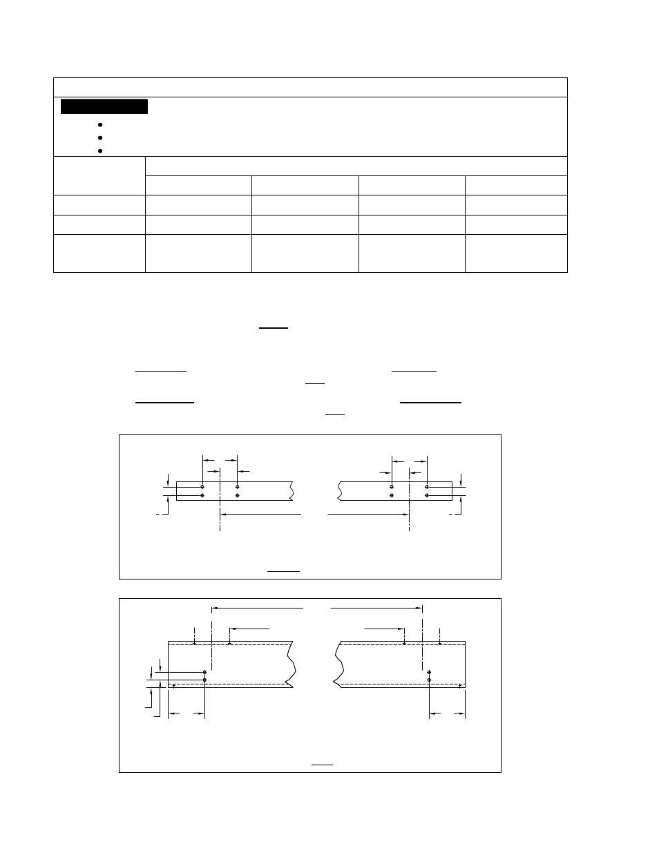
– Drill eight 9/16” diameter holes through the top flange as shown in Figure 3-1. Drill
four 9/16” diameter holes through the web as shown in Figure 3-2.
Top Running
– Drill eight 9/16” diameter holes through the bottom flange as shown in Figure 3-1.
Drill four 9/16” diameter holes through the web as shown in Figure 3-3.
2
1
4
D
2
1
4
D
SPAN
D/2
D/2
Figure 3-1 Bridge Beam Flange Holes
– U
NDERHUNG
&
T
OP
R
UNNING
10
2
2
10
BEAM FLANGE HOLES
(from Fig. 3-1)
SPAN
Figure 3-2 Bridge Beam Web Holes - U
NDERHUNG