Biamp LSI-16e User Manual
Page 9
9
LSI-16/LSI-16e REAR PANEL
Monitored I/O
Two black five-position connectors are located next to the rotary switches. These are predominantly used for monitored inputs and outputs
(I/O) to external lamps or sounders. Individual connections are labeled 1 through 8 as indicated below. One connection is configured for
use as both an input and an output (1) and one as an input (2) (see table below for connector assignments).
The inputs/outputs will sink current (pull low) when active (see the Specifications section of this document for more details). The desired
load (lamp, LED, etc.) must be connected between the input/output terminal and a positive voltage reference.
It should be noted that external switches and a sounder connected to the first two inputs are typically mandatory for standards compliance.
The location and physical attributes of these items may be required to conform with local norms. The switches and sounder must be wired
according to the connection diagram provided below.
For each of these inputs/outputs, a load must be connected between each output and the positive voltage source. If any output on ter-
minals 1 through 8 is unused, the output must be connected through an external resistor to the positive side of the voltage source (either
10V Out or user-supplied external source). To ensure correct functionality, the value of each resistor should be 22kΩ. An internally derived
10V source is provided at the 10V Out terminal; however, the total current available from this pin is limited to 100mA. This voltage source
may be used for external devices provided the total load is less than 100mA. For higher-current devices, a user-supplied external volt-
age source of up to 35V may be used, with the negative side connected to the pin. Due to monitoring constraints, it is impossible to use
both the internal 10V source and an external source. For monitoring purposes, the positive side of the voltage source (either 10V Out or
user-supplied external source) must be connected to the External Supply Over-voltage Monitor (terminal 8), as well as supplying voltage to
external devices.
(I/O 1) Sounder Output/Silence Input
This connection functions as a dual purpose alarm sounder output and silence input (see connection diagram below).
Sounder Output
This output connects to a local sounder for fault and alarm warnings. A sounder is typically required for standards compliance.
Note: If an emergency microphone is located near the sounder, it may be configured in Vocia software to mute the sounder while
making live announcements.
Silence Input
This input is used to silence the local sounder. The sounder will restart in response to any new fault or alarm.
(I/O 2) System Fault Reset Input
This input is required to take the LSI-16/LSI-16e out of System Fault condition. Note: the LSI-16/LSI-16e will always power up in a system
fault state (see connection diagram).
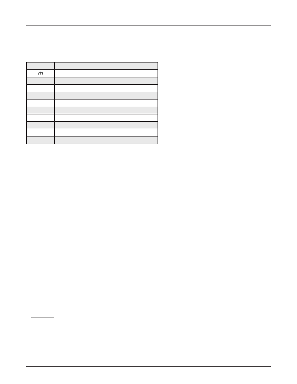
Marking
Function
Ground
1
Sounder Output / Silence Input
2
System Fault Reset Input
3
Voice Alarm Active
4
General Fault
5
PSU Fault
6
Protection Fault
7
Path Fault
8
External Supply Over-voltage Monitor
10V
10V Out