Lsi-16/lsi-16e rear panel – Biamp LSI-16e User Manual
Page 12
12
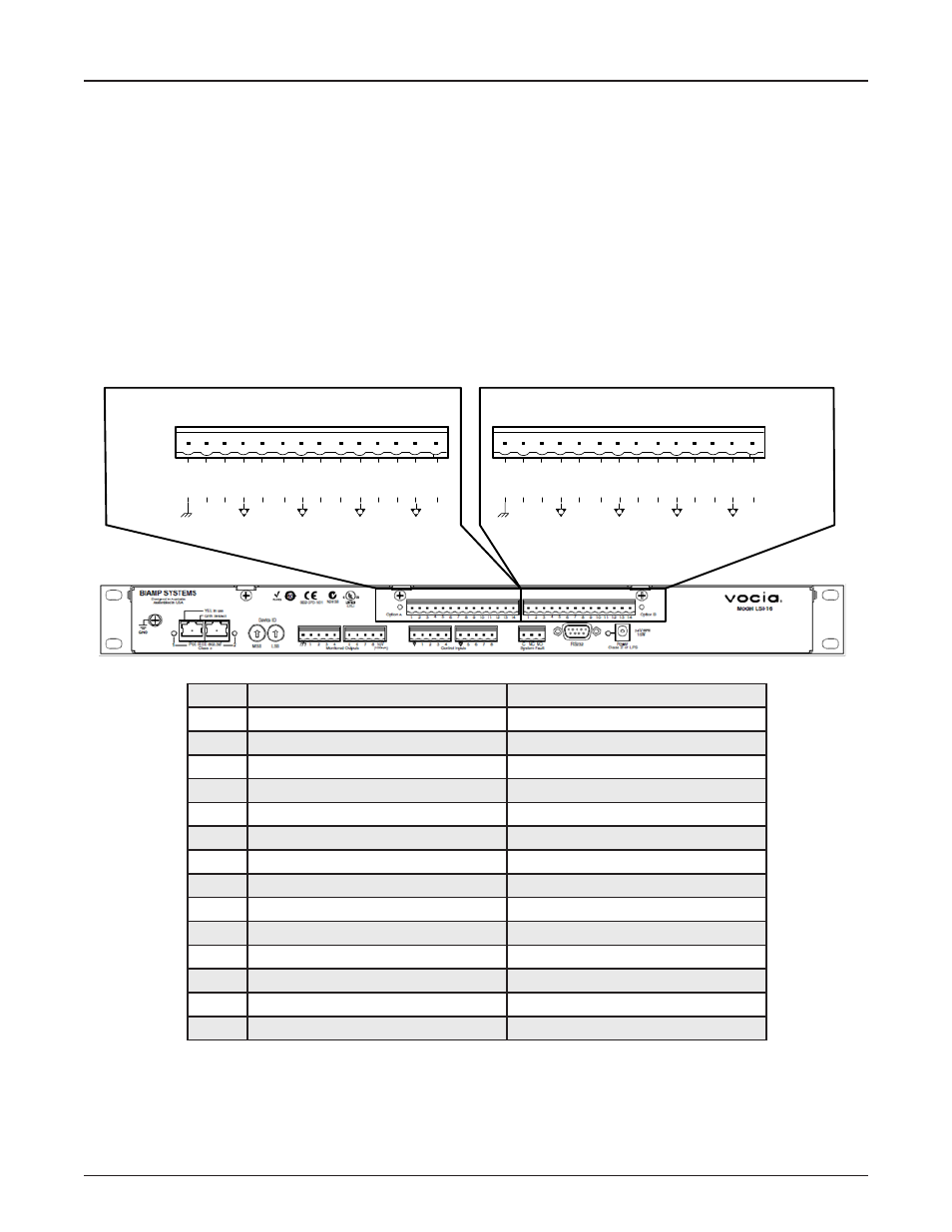
LSI-16/LSI-16e REAR PANEL
General Purpose Inputs
These connections provide functionality of the option inputs on the LSI-16e or of the LSI-16 that has been upgraded with an Interface
Module (IM-16). On an LSI-16 without an option board, these connections will remain inactive.
Two connectors, labeled Option A and Option B, are located on the back of the LSI-16e. Each slot consists of 14 pins which are
labeled 1 to 14. Each connector bank allows for the following connection:
• Chassis Ground: One connection per connector bank.
• Isolated Ground: Four connections per connector bank.
• Control Inputs: Eight connections per connector bank.
24 Volts DC - One output per connector. Internally sourced, this will allow up to 60mA to be shared over all general purpose inputs.
Pin-out
1 2
3 4
6
7 8
24v
5
1 2 3 4 5 6 7 8 9 10 11 12 13 14
1 2 3 4 5 6 7 8 9 10 11 12 13 14
9 10
11 12
14
15 16
24v
13
Option A
Pin
Function
Option B
Pin
Function
Pin
Option A Function
Option B Function
1
Chassis Ground/Shield
Chassis Ground/Shield
2
General Purpose Input 1
Control Input 9
3
General Purpose Input 2
Control Input 10
4
Isolated Ground
Isolated Ground
5
General Purpose Input 3
Control Input 11
6
General Purpose Input 4
Control Input 12
7
Isolated Ground
Isolated Ground
8
General Purpose Input 5
Control Input 13
9
General Purpose Input 6
Control Input 14
10
Isolated Ground
Isolated Ground
11
General Purpose Input 7
Control Input 15
12
General Purpose Input 8
Control Input 16
13
Isolated Ground
Isolated Ground
14
24V (60mA total, shared across all inputs)
24V (60mA total, shared across all inputs)