The start and end of operation, 1 connecting electrical power, 2 connecting the motor – IMP Pumps CL, CLD, CB User Manual
Page 18
-18-
GB
To avoid this danger, the smallest flow
must run through the pump. We ensure
this by installing a bypass or a
circulation to the vessel etc on the
pressure side of the pump. The flow
running through the pump must always
amount to 10% of the flow at the best
working point. We can find the flow and
flow height written on the display plate
with the description of the pump.
• On the pressure side of the piping
system, the system should be balanced
to prevent the occurrence of vacuum.
This is implemented with a special pipe
of diameter 25 mm that is installed
above the highest point of the reservoir
surface level.
• When filling the system with the
medium we must ensure that the
suction piping and the pump are filled
with the medium and all the air is bleed
out. The lock valve from the suction
side, the inflow and outflow pipes, and
the lock valve for vacuum equalising
should all be opened, all the while
controlling the values of the medium
flow, and close the sealing lock fittings.
• The pump may be
installed in an explosion
hazardous area II, but it is
compulsory to additionally
protect the pump against dry
running. This can be done, for
example, with the control of the
pump differential pressure or the
nominal motor current. The pump
should only be used for pumping a
mixture of water and glycol. The use
of solvents is not permitted, as they
could damage the seals.
6. The start and end of
operation
6.1
Connecting
electrical
power
Connection to electricity can
only be done by and
electrician! It is necessary to comply
with the VDE regulations 0100 and for
EX- protection 0165.
Compare the network voltage to the
information on the factory display plate
and choose the right settings.
When connecting, consider the
technical conditions for connecting
to the local supplier of electrical
energy.
We recommend a device for protecting
the motor.
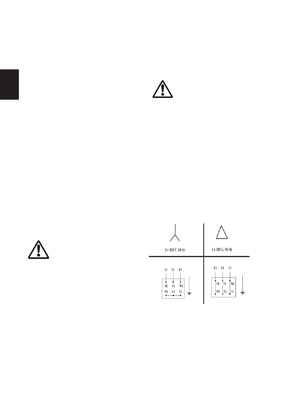
6.2 Connecting the motor
Connect the motor according to the
connection scheme shown in diagram
3.
Diagram 3: Connection Y (high
voltage) and connection ∆ (low
voltage).