IMP Pumps NMT(D) 40-100 & NMT SAN flanges User Manual
Page 21
GB
-21-
To achieve pump IP protection, network cable should be lead over the inlet and then
crimped to a connector. Ethernet plug is galvanicaly insulated, but the rest of the
cabling could still present shock hazard. All connections should be made with the
power turned off.
If more than one pump will be connected into network, each individual pump should
have its IP address and NetBIOS name changed and noted. That will prevent
network collisions and provide naming service in relation to pump function.
5. c
OmmunicatiOn
and
cOntrOl
5.1
c
onTrol
lighT
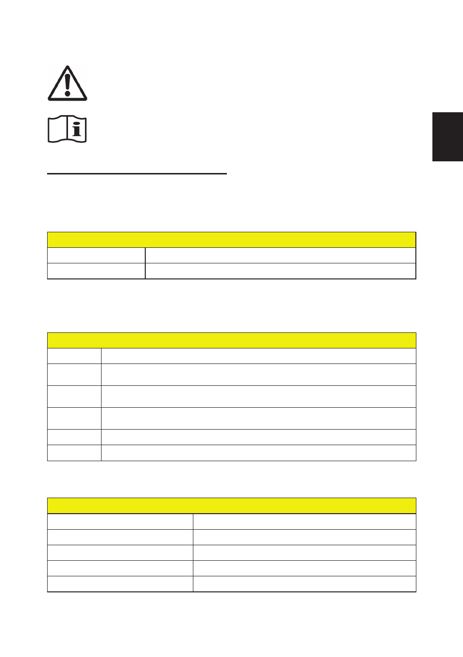
Control light on the front panel provides fast overview over pump operation. Blue color signalizes
correct operation while red indicates an error.
blue light
Blinking
Pump is in standby and not pumping water.
On
Pump is operating as set.
Red light indicates error by blinking error codes. Sequence of blinks is interrupted by a pause.
The number of blinks between two pauses is the error code.
red light
Error code
Description
1
Motor is lightly loaded. This indicates that the pump is probably running dry –
fill the system (might need unairing)
2
Pump can not start. Rotor might be blocked – remove head of pump and
check if the rotor turns freely between hydraulic ceiling and stator
3
Motor has overheated – too hot medium, over isolated head of pump or non-
functioning motor
4
Frequency converter error – pump has or will have error – call professional
5
Stator or rotor faulty – call professional
If the pump is unresponsive, disconnect and connect it back to the electrical grid.
5.2
d
igiTal
inpuTs
Electrical properties
Maximum input voltage
32V DC
Input impedance
~5kΩ
Logical »1« voltage
>8V
Logical »0« voltage
<2V
Insulation
To supply voltage: 4kV@1s, 275V permanent.