System overview, Installation – Velleman SPBS8 User Manual
Page 3
SPBS8
01 (09/10/2008)
Velleman
®
3
Box includes
• 1 LCD display with mounting stand and cable
• 1 front controller unit
• 1 rear controller unit
• 8 sensors
• 4 front sensor cables of 4,5m each, numbered 5~8
• 4 rear sensor cables of 2,5m each, numbered 1~4
• 1 on/off switch with cabling (2,4m)
• 1 power cable for rear ECU
• 1 cable to connect front and rear ECU
• 1 drill Ø18,5mm for sensor mounting
• 1 user manual
• Cable clips
• Double sided adhesive tape
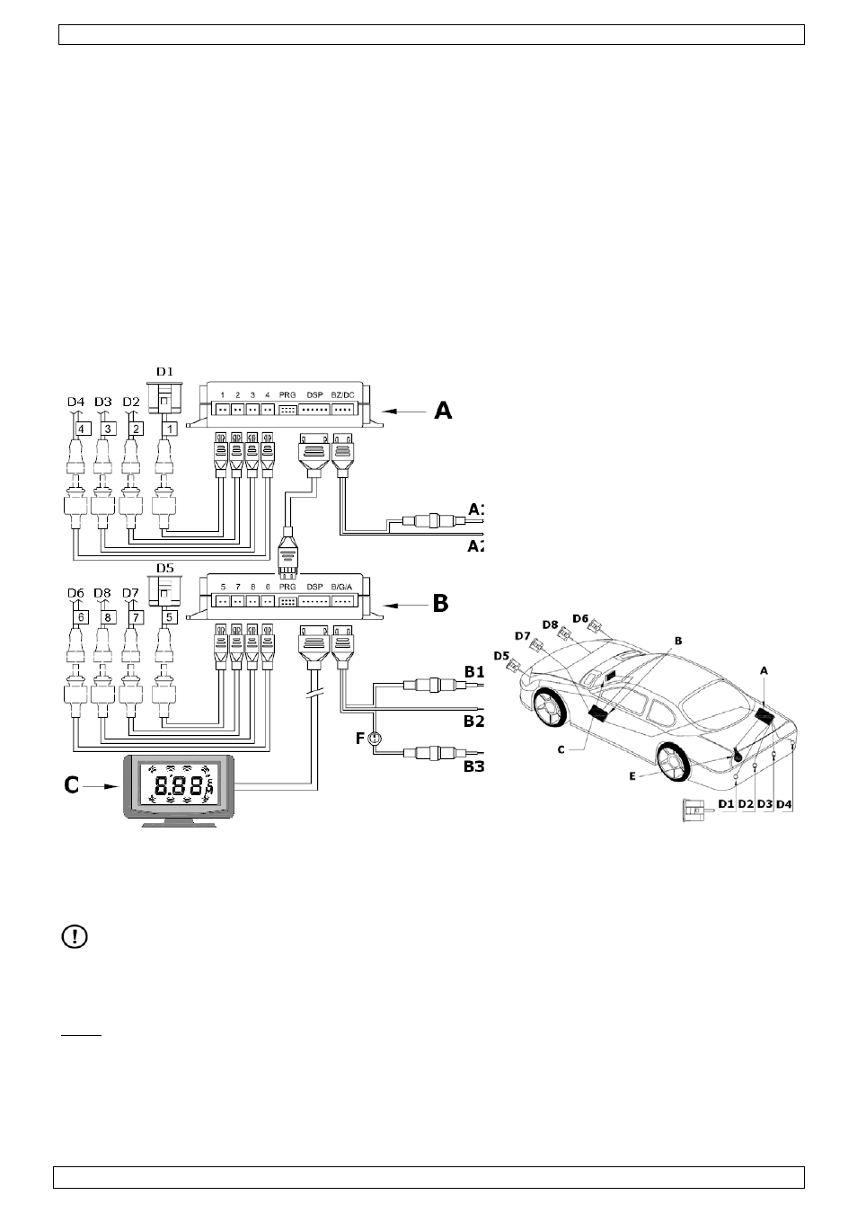
5. System overview
A. Rear Electronic Control Unit
A1. DC +12V (from reverse light)
A2. GND
B. Front Electronic Control Unit
B1. ACC +12V
B2. GND
B3. DC +12V (from brake light)
C. Display unit
D1~D8. Sensor
E. Reverse light
F. On/Off switch
6. Installation
DO NOT apply power to the system before all connections are made.
Sensors
• Choose the location of the sensors on the bumper carefully, as the proper functioning of the
system depends on it.
Note: beware that detection results might be affected when sensors are installed in steel bumpers.
• Refer to the picture below for the best horizontal and vertical position. L=width of the vehicle.