United States Stove Company 1800GC User Manual
Page 11
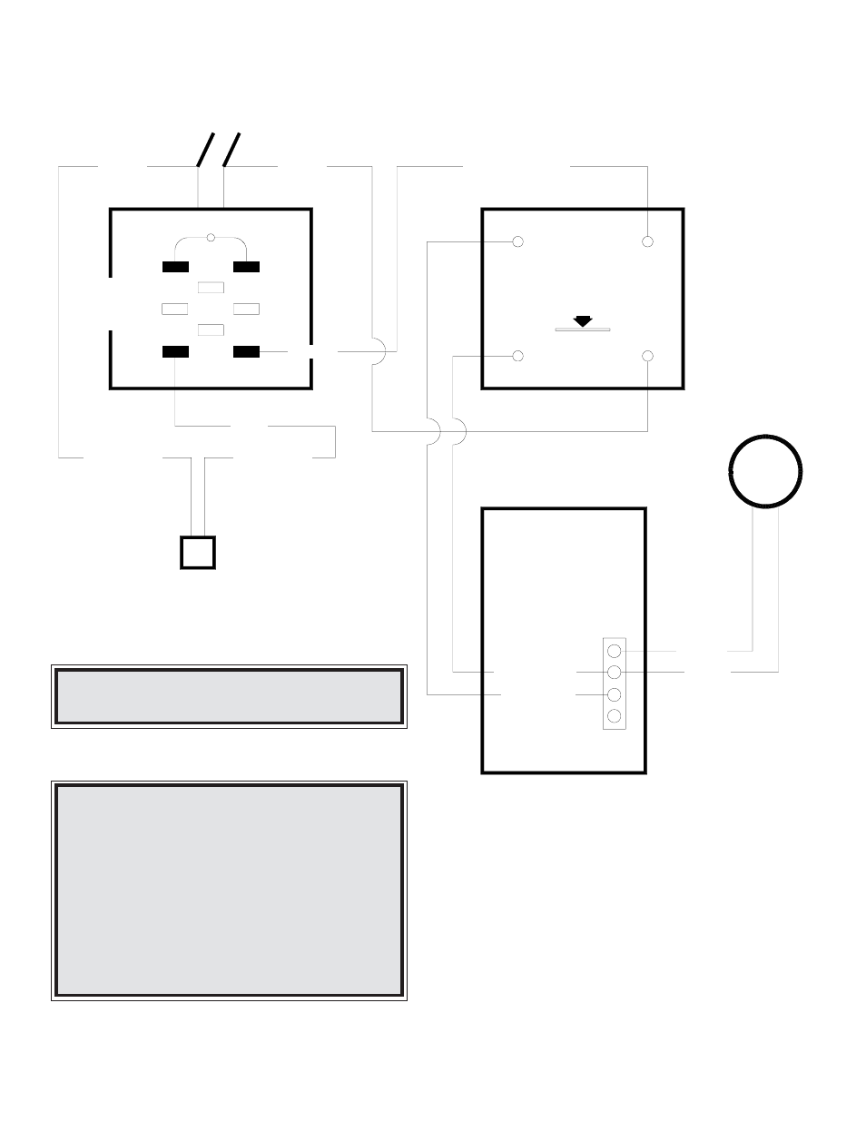
WIRING DIAGRAM FOR SERIES INSTALLATION WITH EXISTING ELECTRIC FURNACE
BLACK
TO BE ADDED
BLUE
BLACK
WHITE
BLACK
MAIN POWER
110 VOLT
BLUE FROM LIMIT
BLACK
BLACK
TO BE
ADDED
HOTBLAST
LIMIT CONTROL
MUST PULL OUT
MUST PULL OUT
MUST PULL OUT
MUST PULL OUT
MUST PULL OUT
THE JUMPER
THE JUMPER
THE JUMPER
THE JUMPER
THE JUMPER
ELECTRIC
FURNACE
THERMOSTAT
ELECTRIC FURNACE
TO "W1"
TO "R"
BLACK TO "R"
RED TO "G"
RED
BLACK WIRE
FROM DRAFT PLUG
WHITE WIRE
FROM DRAFT PLUG
HOTBLAST
COTROL
CENTER
PLUG IN ON THE FRONT
OF HOTBLAST FOR DRAFT
ALL ELECTRICAL WIRING SHOULD BE DONE
BY A QUALIFIED ELECTRICIAN.
NOTE:
Must cut yellow end off draft wires.
NOTE:
DO NOT use three (3) speed switch supplied.
NOTE:
The jumper must be pulled out of the limit
control.
NOTE:
Thermostat wires for the hotblast furnace go
to the front of the control center attach to "R"
and "G".
11