Front panel audio connector: jaudio1, Hardware setup 2-25, Jaudio1 – Premio Computer Aries/Centella User Manual
Page 60
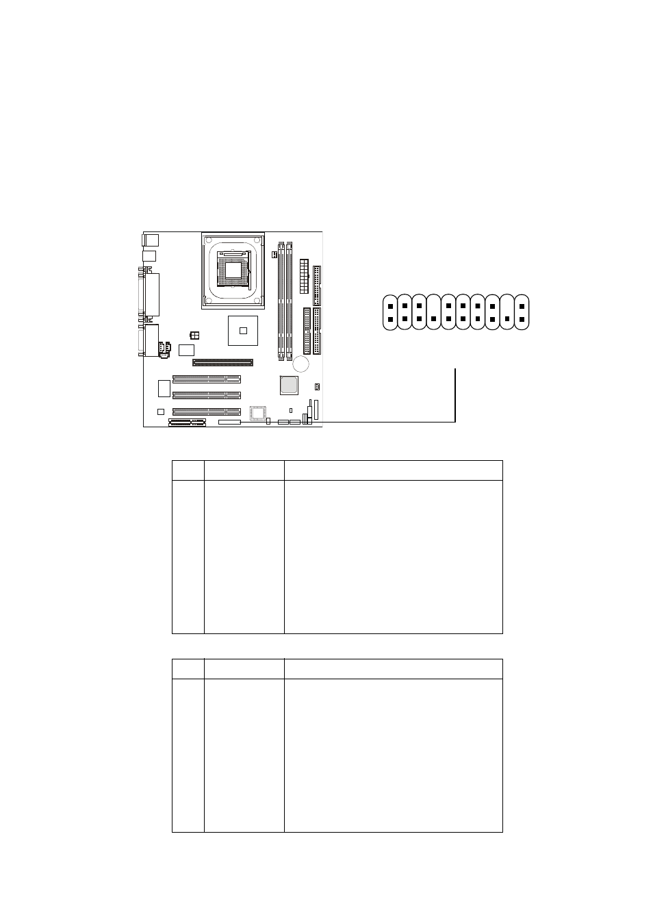
Hardware Setup
2-25
Front Panel Audio Connector: JAUDIO1
You can connect an optional audio connector to the Front Panel Audio
Header. Pin number 1to 10 of the audio pin header is compliant to Intel Front
Panel I/O Connectivity Design Guide.
1
20
JAUDIO1
2
19
10
9
Pin
Signal
Description
1
AUD_MIC
Front Panel Microphone input signal
2
AUD_GND
Ground used by Analog Audio Circuits
3
AUD_MIC_BIAS
Microphone Power
4
AUD_VCC
Filtered +5V used by Analog Audio Circuits
5
AUD_FPOUT_R
Right Channel Audio signal to Front Panel
6
AUD_RET_R
Right Channel Audio signal Return from Front Panel
7
HP_ON
RSVD for future use to control Headphone Amplifier
8
NC
No Connection
9
AUD_FPOUT_L
Left Channel Audio signal to Front Panel
10
AUD_RET_L
Left Channel Audio signal Return from Front Panel
JAUDIO1 Pin Definition (1~10)
Pin
Signal
Description
11
AUD_MIC
Front Panel Microphone input signal
12
AUD_GND
Ground used by Analog Audio Circuits
13
AUD_FPOUT_R
Right Channel Audio signal to Front Panel
14
AUD_RET_R
Right Channel Audio signal Return from Front Panel
15
AUD_FPOUT_L
Left Channel Audio signal to Front Panel
16
AUD_RET_L
Left Channel Audio signal Return from Front Panel
17
AUD_GND
Ground used by Analog Audio Circuits
18
NC
No Connection
19
LINE-IN-R
Line in Right
20
LINE-IN-L
Line in Left
JAUDIO1 Pin Definition (11~20)