Sample configuration: links crossing ip routers – Symantec Veritas 5 User Manual
Page 163
link link1 udp - udp 50000 - 192.1.2.2 192.1.2.255
link link2 udp - udp 50001 - 192.1.3.2 192.1.3.255
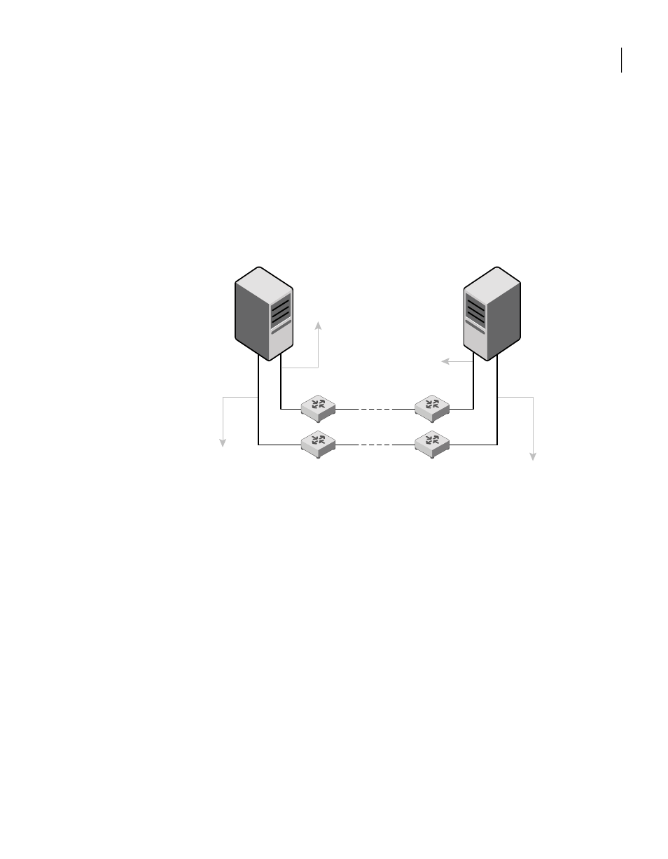
Sample configuration: links crossing IP routers
depicts a typical configuration of links crossing an IP router employing
LLT over UDP. The illustration shows two nodes of a four-node cluster.
Figure A-2
A typical configuration of links crossing an IP router
UDP Endpoint eth2;
UDP Port = 50001;
IP = 192.1.2.1;
Link Tag = link2
UDP Endpoint eth1;
UDP Port = 50000;
IP = 192.1.3.1;
Link Tag = link1
eth1;
192.1.2.2;
Link Tag = link2
eth2;
192.1.3.2;
Link Tag = link1
Routers
Node0 at Site A
Node1 at Site B
The configuration that the following
/etc/llttab
file represents for Node 1 has
links crossing IP routers. Notice that IP addresses are shown for each link on each
peer node. In this configuration broadcasts are disabled. Hence, the broadcast
address does not need to be set in the
link
command of the
/etc/llttab
file.
set-node Node1
set-cluster 1
link link1 udp - udp 50000 - 192.1.3.1 -
link link2 udp - udp 50001 - 192.1.4.1 -
#set address of each link for all peer nodes in the cluster
#format: set-addr node-id link tag-name address
set-addr
0 link1 192.1.1.1
set-addr
0 link2 192.1.2.1
set-addr
2 link1 192.1.5.2
set-addr
2 link2 192.1.6.2
163
Advanced VCS installation topics
Using the UDP layer for LLT