Communications pin-out configurations – Intermec PK80 User Manual
Page 52
Troubleshooting
Chapter
—
4
40
PK80 Series 80-Column User’s Manual
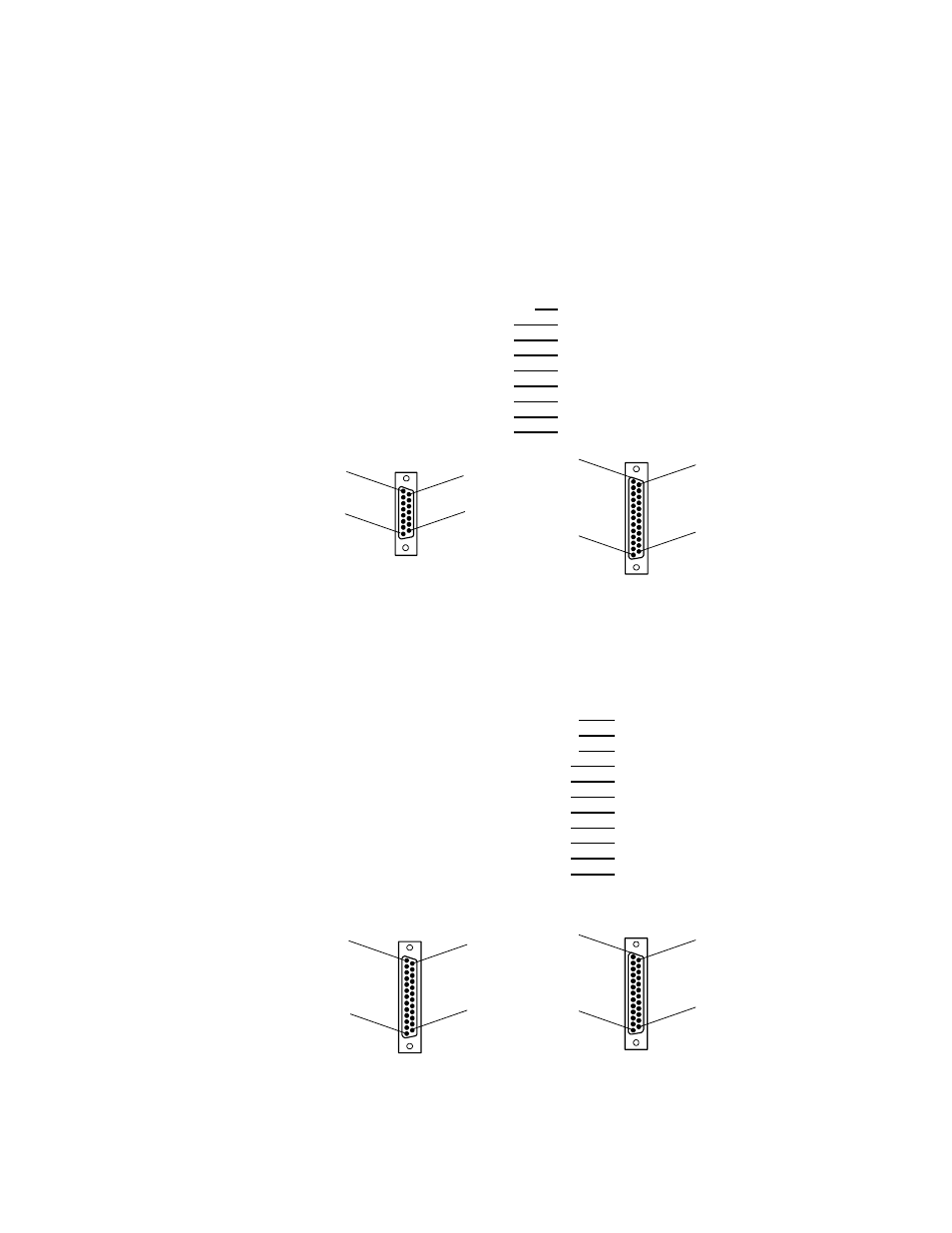
Communications Pin-Out Configurations
Below are common cable configurations between a mobile computer or a
dock and the printer:
Signal Name
Pin #
Pin #
Signal Name
Chassis Ground
shell
1
NC (No Connection)
Charge Input
8
9
HHC_CHARGE
SG (Signal Ground)
9
7
GND
DSR (Data Set Ready)
7
6
NC
DTR (Data Terminal Ready)
2
20
NC
CTS (Clear To Send)
6
5
RTS
RTS (Ready To Send)
3
4
CTS
RXD (Receive Data)
5
3
TXD
TXD (Transmit Data)
4
2
RXD
13
Mobile Computer
Fixed Mount Printer or
Remote Mount Terminal Holder
25-Pin DSUB Male
1
25
14
8
15-Pin DSUB Male
15
9
1
shield
15-Pin to 25-Pin Cable
P/N: 216-605-XXX
PC
Fixed Mount Printer
Signal Name
Pin #
Pin #
Signal Name
DTR (Data Terminal Ready)*
20
20
NC (No Connection)
RC (Receive Carrier)*
17
17
NC
TC (Transmit Carrier)*
15
15
NC
DCD (Data Carrier Detect)*
8
8
NC
SG (Signal Ground)
7
7
GND
DSR (Data Set Ready)*
6
6
NC
CTS (Clear To Send)
5
5
RTS
RTS (Ready To Send)
4
4
CTS
RXD (Receive Data)
3
3
TXD
TXD (Transmit Data)
2
2
RXD
Chassis Ground
1
1
NC
* Signals are not available on the 6100 Dock
13
25-Pin DSUB Male
25-Pin DSUB Female
1
13
1
14
25
25
14
25-Pin to 25-Pin Cable
P/N: 216-771-XXX