Online power – IBM Fire Alarm Back-up UPS1481 UNIT User Manual
Page 12
OnLine Power
(6002-1646) REV.X8
6
1-4 CUSTOMERS
CONNECTIONS
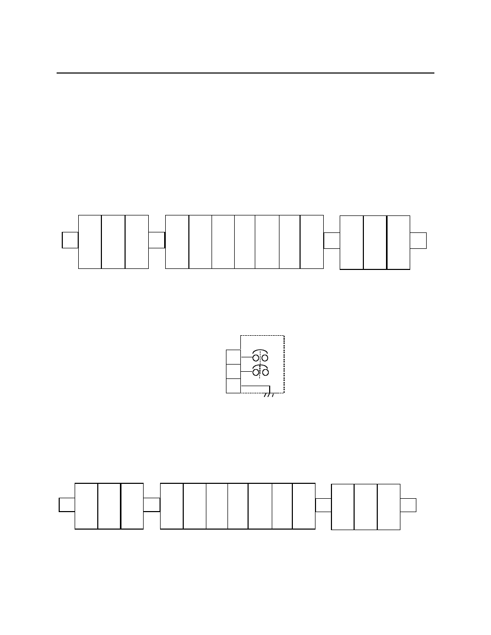
1-4-1 Input Power Connection by Customer (with no input C/B option)
Connect input (Hot) at TB-1
Connect input Hot / Neutral at TB1-2
Connect input ground at TB1-3
Input wirings for various input voltages are same.
When input cirucit breaker is used, input CB1 is installed in inside of the UPS.
1
3
2
CB1
INPUT
TB1
CUSTOMER
WIRES
TO CB1
PROTECTOR CUSTOMER'S CONNECTION TERMINAL BLOCK
ILLUSTRATION 1-6
(From External Battery Cabinet)
1
HOT
2
HOT
(
N
)
3
GND
1
OV
2
120V
3
OV
4
5
120V
6
7
GND
1
(+)
2
(-)
3
GND
INPUT
(
TB
1
)
(
TO CUSTOMER
’
S LOAD
)
OUTPUT
(
TB
2)
BATTERY
CONNECTION
(
TB
3)
PROTECTOR CUSTOMER
’
S CONNECTION TERMINAL BLOCK
ILLUSTRATION
1 - 5
(From External Battery Cabinet)
1
HOT
2
HOT
(
N
)
3
GND
1
OV
2
120
V
3
OV
4
5
120
V
6
7
GND
1
(+)
2
(-)
3
GND
INPUT
(
TB
1)
(
TO CUSTOMER
’
S LOAD
)
OUTPUT
(
TB
2)
BATTERY
CONNECTION
(
TB
3)