Wiring the ex-2714 system cable – Icom MR-1000TTM User Manual
Page 31
27
9
INSTALLATION AND CONNECTIONS
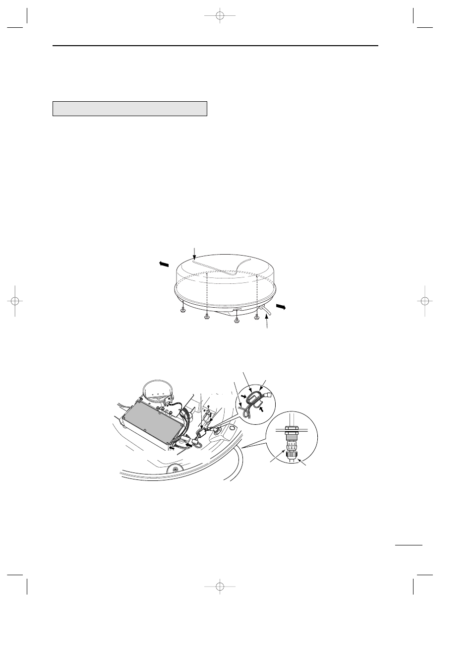
■ Wiring the EX-2714 system cable
q Loosen the four bolts using a hex head wrench on
the bottom of the scanner unit, and open the unit.
w Loosen the nut on the scanner unit and pass the
system cable through the nut and sealing tube.
e Insert the PA cable (black and white) connector to
the PA unit connector J1. (*1; Be sure to follow the
following diagram carefully)
r Connect the shielding wire to the ground plate with
the screw as shown in the diagram.
t Clamp the system cable with the ferrite bead at-
tached near the sealing connector. Be sure to clamp
it tightly.
• Scanner unit disassembly
y Connect the power cable (black and red) end to the
power unit connector. (*2; Be sure to follow the fol-
lowing diagram carefully).
u Tighten the sealing-nut, then replace the radome
cover over the scanner unit.
DO NOT stretch the system cable too much, other-
wise miss contact of the connector may occur.
i Tighten the four bolts on the bottom of the scanner
unit.
• The four projections around the circumference of
the radome cover show the positions of the bolt
receptacles.
CAUTION:
NEVER cut the supplied system cable.
Ship’s bow direction
Face the Ω mark in the direction
of the ship’s bow.
Stern
System cable
Scanner unit disassembly
• Connect the system cable
Ferrite bead
Shielding
wire
PA cable
Power cable
Round the PA
cable twice.
Sealing tube
Nut
*2; Power
connector
*1; PA cable
MR-1000R2_T2.qxd 04.2.24 10:22 Page 27