Installing the display unit, Installation and connections, W drill 5 holes of 3 mm – Icom MR-1000TTM User Manual
Page 29
• SX-2713/2779
MARINE RADAR
269 (10
19
⁄
32
)
258 (10
5
⁄
32
)
48 (1
29
⁄
32
)
264 (10
13
⁄
32
)
287 (1
1
7
⁄
16
)
132 (5
3
⁄
16
)
132 (5
3
⁄
16
)
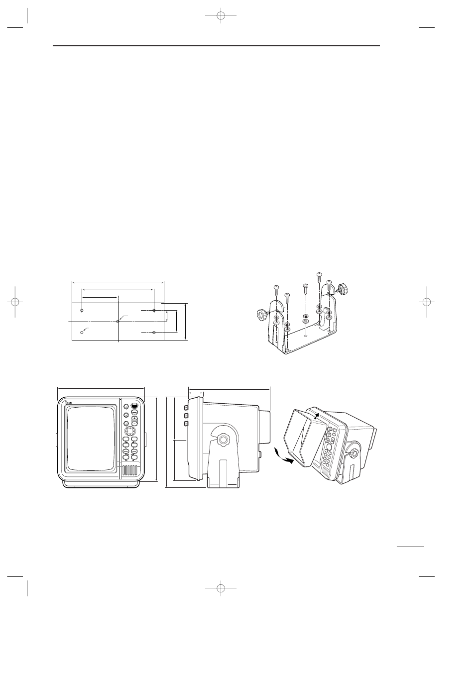
• Viewing hood installation
• SX-2713/2779 Mounting Bracket
• Mounting Bracket installation
Fig. 2
250 (9
27
⁄
32
)
195 (7
11
⁄
16
)
97.5 (3
27
⁄
32
)
100 (3
15
⁄
16
)
60 (2
3
⁄
8
)
30 (1
3
⁄
16
)
Ш7 (
9
⁄
32
)
Ч4
Ш7 (
9
⁄
32
)
Fig. 1
9
INSTALLATION AND CONNECTIONS
25
■ Installing the display unit
D Location
Select a place for installation which meets the following
important conditions:
q The display unit should be placed near the wheel in
the cabin so that an operator may easily view the
radar screen while facing the bow.
w To minimize interference, KEEP the unit AT LEAST
THE COMPASS SAFE DISTANCE stated in the se-
rial No. seal on the rear panel away from the com-
pass and navigation receiver.
e Select a position where there is no danger of salt or
fresh water spray or immersion.
r Select a location where it is easy to perform main-
tenance or adjustment after installation.
t Select a location which can support the weight of
the display unit.
y DO NOT select areas subject to extreme heat, cold,
vibrations or direct sunlight.
D Mounting
The mounting bracket supplied with the display unit al-
lows “dashboard” or “overhead” mounting.
q Hold the mounting bracket up to the selected loca-
tion and mark pilot holes for the 5 installation holes
using the template.
• The template is provide on p.41.
w Drill 5 holes of 3 mm (
1
⁄
8
in) in diameter as shown
in the diagram. (Fig. 1)
e Install the bracket using the screws, nuts, bolts or
washers, with the supplied accessories. (Fig. 2)
r Adjust the display unit to an adequate view angle.
t Install the supplied viewing hood.
MR-1000R2_T2.qxd 04.2.24 10:22 Page 25