3a 3e 3b 3c, 3d 5b 5c, Step 3 – handlebar tube assembly – Fitness Quest NBP01060-2 User Manual
Page 8: Step 4 – foot pedal assembly, Step 5 – handlebar assembly
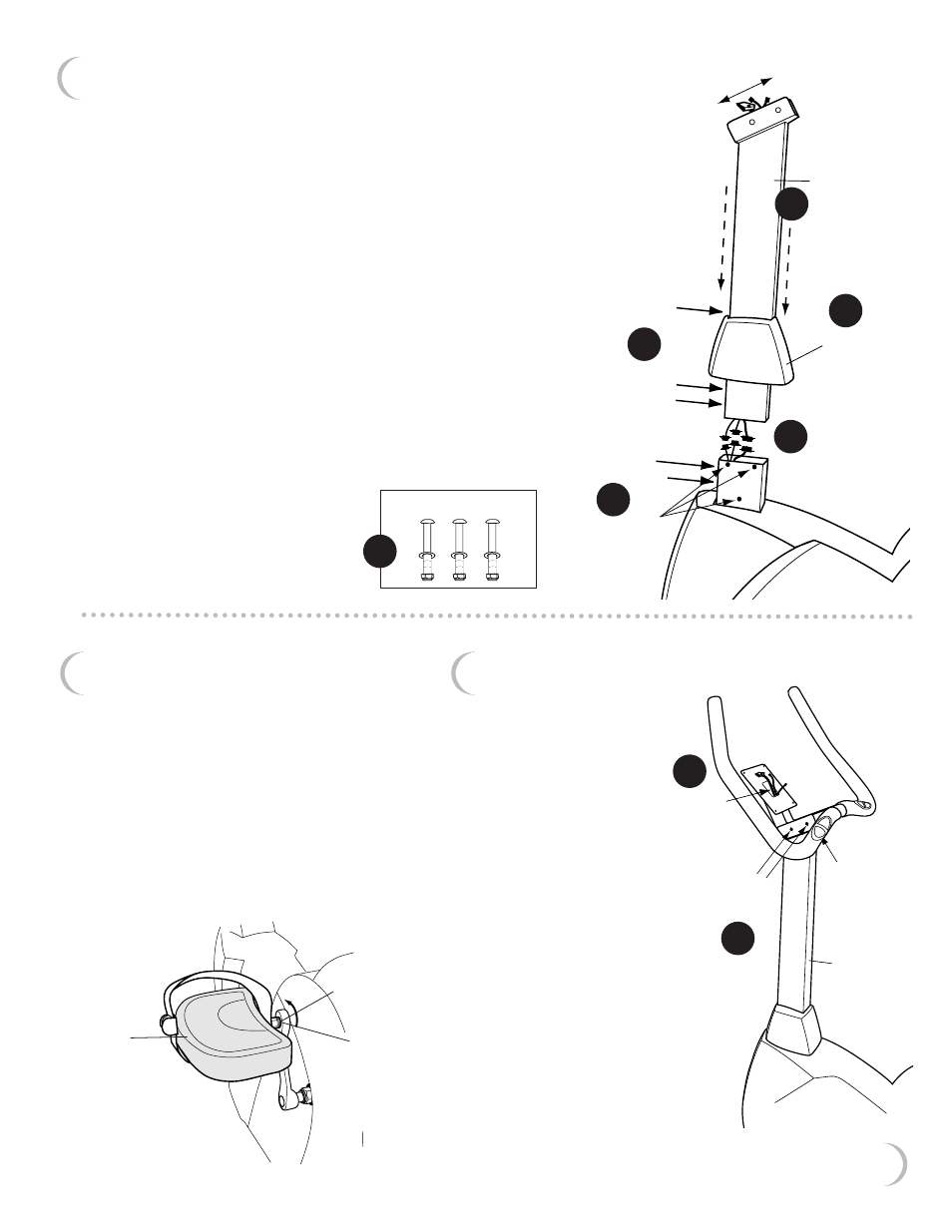
STEP 3 – Handlebar Tube Assembly
a) Remove the two Allen Bolts, Washers and Phillips Screw from the
front of the Handlebar Tube.
b) Slip the Handlebar Tube Cover onto the Handlebar Tube as shown.
c) Remove the wire tie from the wires inside the neck of Main Frame
Assembly where the Handlebar Tube will go. Attach the three
wires from the Main Frame Assembly to the three wires coming
out the bottom of the Handlebar Tube. Handlebar Tube should
angle down towards the front of the unit.
d) Insert the Handlebar Tube into the neck of the Main Frame
Assembly tucking the wires down into the Main Frame
Assembly. Be careful not to pinch the wires. Gently pull the
wires up from the top of the Handlebar Tube to prevent any
slack in the wires at the base of the Handlebar Tube.
e) Secure the Handlebar Tube in place with the three
Carriage Bolts, Washers and Nylon Nuts from the
fastener pack. Tighten with the Wrench provided.
Reinsert the Bolts and Washers you removed in (a).
Tighten with the Allen Wrench provided.
f)
Let the Handlebar Tube Cover
slip into place. Push it down
gently until it clicks.
Secure with the Phillips
Screw you removed in (a)
and tighten.
M8 x 60mm carriage bolts,
M8 washers and M8 nylon nuts
STEP 4 – Foot Pedal Assembly
The Foot Pedals and the Foot Pedal
Cranks are marked “L” and “R”.
Using the Wrench provided, attach
the Left Foot Pedal to the Left Crank
rotating the Wrench counter-clockwise.
Do not try to turn clockwise. You will strip
the threads.
Attach the Right Foot Pedal to the Right
Crank rotating the Wrench clockwise.
handlebar
tube
angle down
towards front
carriage bolts,
washers & nuts
from fastener
pack
main frame
assembly
handlebar
tube cover
remove
allen bolts
& washers
insert bolts
& washers
removed in 3a
remove
phillips screw
3a
3e
3b
3c
left side shown
looking from the
back of the unit
STEP 5 – Handlebar Assembly
a) Remove the two
Allen Bolts, Washers
and Nuts from
Handlebars. Also,
remove the Allen
Bolt on the
underside of
the Handlebar.
b) Feed the wires up
through the base
of the Handlebar
so they come out
the top.
c) Place Handlebars into “U”
on the top of the Handlebar
Tube. Remove the Nut Caps.
Replace and tighten the
three Allen Bolts, Washers
and Nylon Nuts you just
removed with the Wrench
provided. Replace the
the Nut Caps.
replace
bolts, washers
and nuts
replace
bolt
feed wires
through here
handlebar
tube
7
left
crank
“L” & “R”
markings
are shown
on the ends
of the
pedal shafts
left
foot
pedal
3d
5b
5c
front
3e