Hand Held Products 5700 User Manual
Page 81
7–5
SCANTEAM 5700 User’s Guide
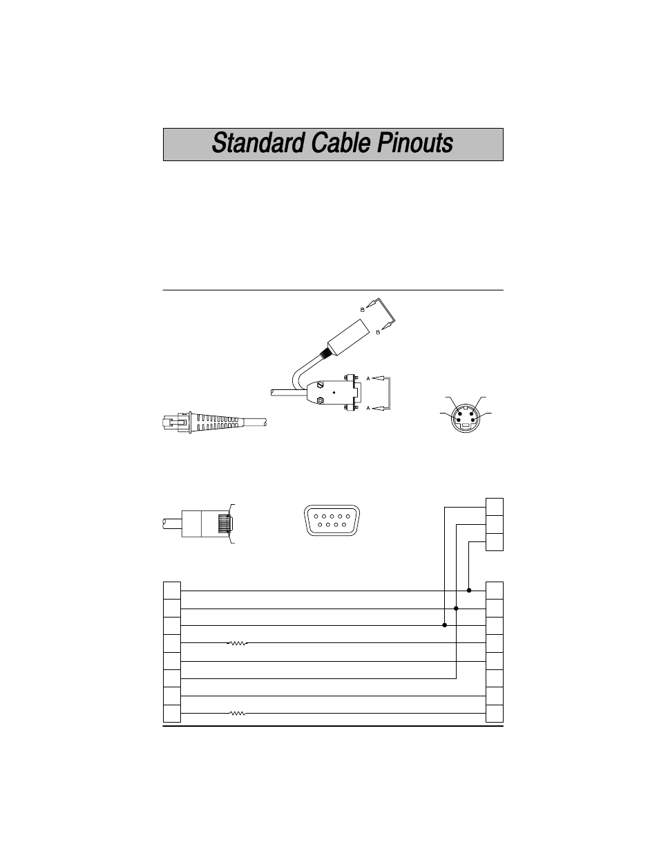
RS–232
5700–X1, 5700–X2 (TTL) and 5700–X3 (True)
Decoded output data format is provided at the modular connector in the scanner
handle.
Signal
Function
Interface cables normally supplied with scanner model 5700–X1, 5700–X2
(TTL), and 5700–X3 (True) are terminated with an 10 pin modular plug (P1) and
a 9 pin Type D connector (P2) that is compatible with all Welch Allyn terminals.
See chart below.
9
7
8
4
3
5
6
2
SH
6
5
2
8
7
3
P2
9 Pin Type D Female
6
9
1
5
+5VDC
RTS
Ground
DTR
RXD
TXD
Braid
Clear to Send Data
5 Volt Power Connection
Request to Send Data
Supply Ground
Data Terminal Ready
Receive Data – Serial Data to Scanner
Transmit Data – Serial Data from Scanner
Cord Shield
CTS
P1
P2
View A–A
P2 connects to
your terminal.
470
Ω
470
Ω
SH
1
2
P3
P3
4 Pin Type Mini–DIN
1
2
3
4
View B–B
P3 connects to
the external
power supply.
P1
10 Pin Modular Plug
Pin 1
Pin 10
P1 connects to the
scanner handle.