Functional description, Initial tool set up/ assembly, Specifications – Harbor Freight Tools 97870 User Manual
Page 8: Unpacking, Air supply
Page 8
SKU 97870
For technical questions, please call 1-800-444-3353.
FUNCTIONAL DESCRIPTION
Specifications
Exhaust Position
Frontal Exhaust
On/Off Method
Built-in Rotary Valve
Air Inlet
1/4" -18 NPT (male inlet
coupler)
Maximum Speed*
25,000 RPM
Air Consumption
2 CFM @ 90 PSI
Collet Size
1/8"
* Maximum speed at stated maximum air pressure. Ex-
cess air pressure is hazardous and may cause the tool
to exceed stated maximum speed.
INITIAL TOOL SET UP/
ASSEMBLY
Read the ENTIRE IMPORTANT
SAFETY INFORMATION
section at the beginning of this
manual including all text under
subheadings therein before set
up or use of this product.
Note: For additional information regarding
the parts listed in the following pages,
refer to the Assembly Diagram near
the end of this manual.
Unpacking
When unpacking, check to make sure
that the item is intact and undamaged. If
any parts are missing or broken, please
call Harbor Freight Tools at the number
shown throughout the manual as soon as
possible.
• This air tool may be shipped with a
protective plug covering the air inlet.
Remove this plug before set up.
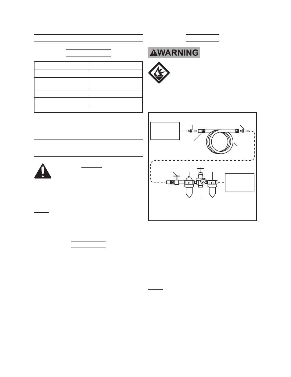
Air Supply
TO PREVENT
EXPLOSION:
Use only clean, dry, regulated,
compressed air to power this
tool. Do not use oxygen,
carbon dioxide, combustible
gases, or any other bottled
gas as a power source for this
tool.
1.
Tool
Air
Compressor
Quick
Coupler
Air Hose
on Reel
Filter
Regulator with
Pressure Gauge
Male
Connector
Male
Connector
Valve
Quick
Coupler
Recommended Air Line Components
Oiler
Incorporate an in-line oiler, shut-off
valve, regulator with pressure gauge,
and filter for best service, as shown in
the diagram above.
An in-line shut-
off valve is an important safety
device because it controls the air
supply even if the air hose is rup-
tured.
Note: If an automatic oiler system is not
used, add a few drops of Pneumatic
Tool Oil to the airline connection be-
fore operation. Add a few more drops
after each hour of continual use.
2. Attach an air hose to the compres-
sor’s air outlet. Connect the air hose
to the air inlet of the tool. Other com-
REV 08j