Warning, Fig. g, Installing – Hitachi CB 13F User Manual
Page 13: Fig. h
—
—
13
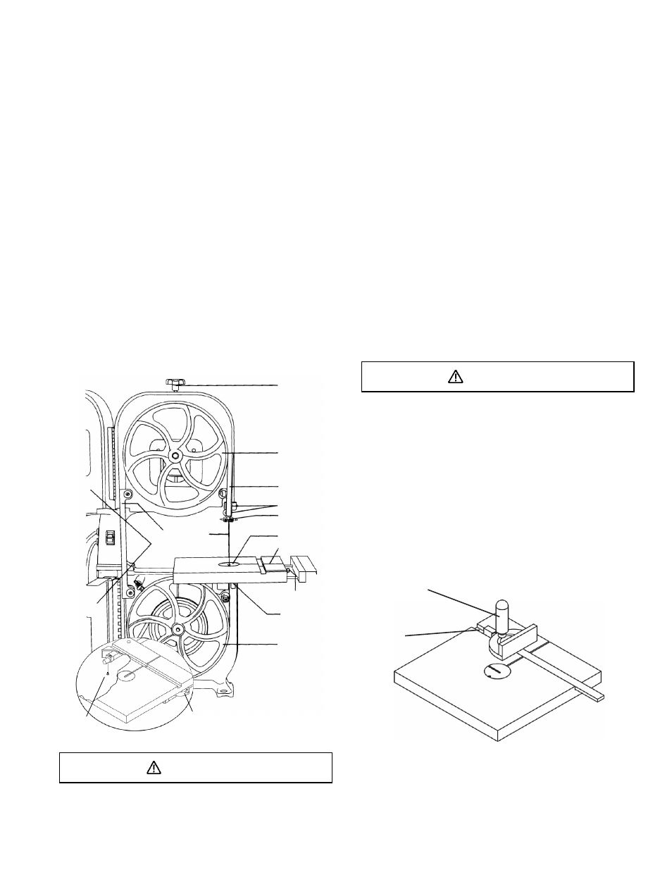
INSTALLING AND REMOVING THE BLADE(Fig.G)
WARNING!
To avoid injury from accidental starting, always turn the
switch OFF and remove the plus from the power source
before moving, replacing, or adjusting the blade.
Removing
1. Loosen the blade tension by turning the blade tension
knob (1) counterclockwise.
2. Remove the table insert (2) and the table aligning
pin (3) from the table.
Unlock the lock knobs (12) under the table. Unfasten
the screw (13) at the right of extension tube and
remove the extension table from the table.
3. Open up wheel cover door (4).
4. Loosen the two Phillips screws (5) and remove the
upper blade guard (6).
5. Release the lock knobs (12) under the table, then
remove the screw (13) at the right of extension tube
and the extension table.
6. Remove the blade (7) from the upper and lower blade
guides (8).
7. Carefully pull the blade from the side slot (9) and from
the wheels (10).
8. Swing the left side of the blade toward you, turning
the blade so it will fit through the slot (11) in the table,
and remove.
Fig. G
1
6
5
8
2
11
8
3
7
9
4
10
12
13
10
WARNING
Before operation always make sure the blade is in center
of table insert slot.
Installing
1. Make sure the blade tension knob (1) turned
counterclockwise until it stops.
2. Remove old blade as explained in "Removing".
3. Guide the new blade teeth are pointing forward and
down.
NOTE: To avoiding lifting the workpiece, the blade
teeth must point downward toward the table.
4.
Swinging the left side off the blade away and back,
place the blade on the upper and lower wheels (10).
5.
Place the blade carefully between the upper and lower
blade guides (8).
6.
Slide the blade into the slot (9) at the left of the
wheels, and make sure the blade is positioned at the
middle of the wheels.
7.
Turning the blade tension knob (1) clockwise, tighten
the tension until the blade is tight on the wheels.
8.
Replace the table insert (2) and the table aligning pin (3).
Install the extension table and fasten the screw (13) at
the right of extension tube. Lock the lock knobs (12)
under the table.
9. Adjust the blade tracking and tension properly (See
ADJUSTMENT INSTRUCTIONS section) before
operation the band saw.
WARNING
To avoid injury, the blade tension, tracking, and upper and
lower guides and bearings must be properly adjusted
before operating the band saw. (See ADJUSTMENT
INSTRUCTIONS section)
MITER GAUGE (Fig. H)
A miter gauge (1) is supplied with your band saw to be
used in the table slot (2) on the right side of the blade. The
miter gauge can be tilted 0 to 45 deg. right or left to maintain
an accurate angle for your workpiece. A bracket is
provided on the leg stand for convenient miter gauge
storage.
Fig. H
1
2