Grinding wheel assembly – Harbor Freight Tools 6510 User Manual
Page 11
Page 11
For technical questions, please call 1-800-444-3353.
SKU 6510
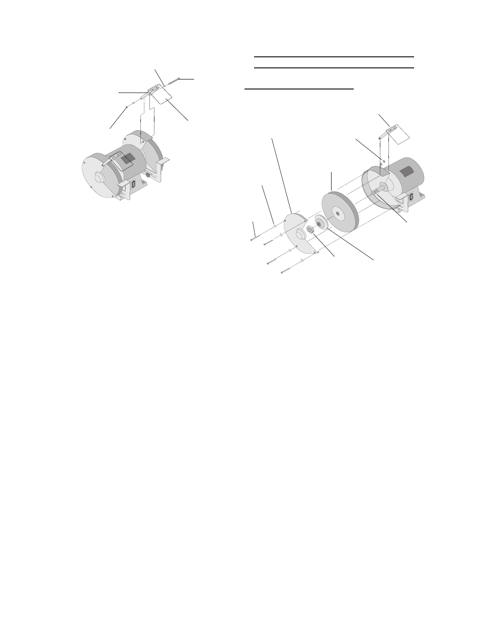
FiGure 4 –
attaching the eye Shield
to Wheel cover
Shield
Supports
(4)
nut
(13)
Washers
(14)
Bolt
(12)
eye
Shield
(3)
2. Remove the BOLT (12) and NUT (13)
from the upper grinder housing as
shown in Figure 4.
Align the EYE SHIELD Assembly
3.
with holes and replace the WHEEL
COVER BOLT and NUT.
Adjust the EYE SHIELD to the de-
4.
sired position and tighten the WHEEL
COVER NUT.
GrindinG Wheel aSSemBlY
remove Grinding Wheel
FiGure 5 – assembling the Grinder
Washers
(14)
eye
Shield (3)
nut (13)
Grinding
Wheel (2)
Wheel
cover (6)
Spindle
(9)
Wheel
mounting
Washer (11)
Wheel
mounting
nut (10)
Bolt
(12)
1. Remove both GRINDING WHEEL
COVERS (6) by unscrewing their
BOLTS (12) and NUTS (13) as shown
in Figure 5.
Place adjustable wrenches on both
2.
WHEEL MOUNTING NUTS (10).
To remove the right hand GRINDING
3.
WHEEL (2) turn its WHEEL MOUNT-
ING NUT clockwise while keeping the
left hand WHEEL MOUNTING NUT
stationary. To remove the left hand
GRINDING WHEEL turn its WHEEL
MOUNTING NUT counterclockwise
while keeping the right hand WHEEL
MOUNTING NUT stationary.
Slide the WHEEL MOUNTING
4.
WASHER (11) off of the SPINDLE
(9).
Slide the GRINDING WHEEL off of
5.
the SPINDLE (9).