2e assembly, Assembly step 6, Assembly step 7 you’re finished – Horizon Fitness 2.2E User Manual
Page 6
BEFORE
YOU
BEGIN
10
INTRODUCTION
IMPORT
ANT
PRECAUTIONS
ASSEMBL
Y
BEFORE
YOU
BEGIN
ELLIPTICAL
OPERA
TION
LIMITED
W
ARRANTY
TROUBLESHOOTING
&
MAINTENANCE
CONDITIONING
GUIDELINES
BEFORE YOU
BEGIN
ASSEMBL
Y
11
INTRODUCTION
IMPORT
ANT
PRECAUTIONS
ELLIPTICAL OPERA
TION
CONDITIONING GUIDELINES
TROUBLESHOOTING &
MAINTENANCE
LIMITED WARRANTY
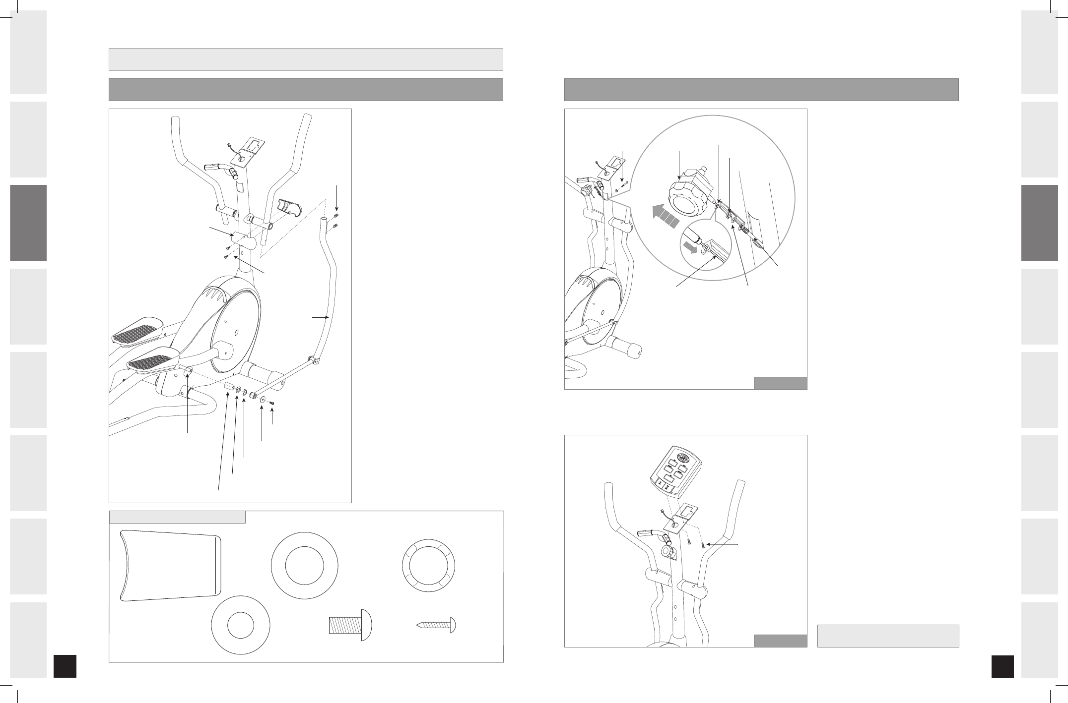
1.2E ASSEMBLY
A) Open
HARDWARE BAG FOR STEP 6.
B) To attach
LOWER LINK ARM to
PEDAL ARM, slide SPACER (J),
FLAT WASHER (K) and WAVY
WASHER (L) onto PEDAL ARM
BRACKET.
NOTE: Attaching the lower link arm
assembly to the pedal arm first
makes assembly of the linkage
arms less difficult.
C) Slide
LOWER LINK ARM onto
PEDAL ARM BRACKET, followed by
FLAT WASHER (M) and
BOLT (N).
D) Repeat on other side.
E) Slide
LOWER LINK ARM onto
UPPER HANDLEBAR and attach
using 2
PRE-ATTACHED SET
SCREWS.
F) Attach
HANDLEBAR COVERS using
2
SCREWS (O).
G) Repeat on other side.
����������
���������������
������������
����������
��������������
��������
���������������
���������������
���������������
����������
�����������������
����������
����������
������
���������������
�����
������
����
����������
�����
������
��������
�����
������
���������
�����
������
����
����������
�����
������
HARDWARE BAG FOR STEP 6 CONTENTS :
ASSEMBLY STEP 6
NOTE: There is NO hardware bag
for this step. All hardware is pre-
installed.
A) Pull
TENSION CABLE out from
square hole in console mast.
B) Turn
RESISTANCE KNOB to highest
resistance setting. Place the
TENSION WIRE into the BOTTOM
KEY HOLE on the RESISTANCE
KNOB BRACKET.
C) While holding the
RESISTANCE
KNOB BRACKET, pull the
RESISTANCE KNOB up to slide it
into the
TOP KEY HOLE position on
the
RESISTANCE KNOB BRACKET.
D) Once the
TENSION WIRE is in
position, turn the
RESISTANCE
KNOB to the lowest resistance
setting.
E) Slide
RESISTANCE KNOB &
BRACKET into the CONSOLE MAST
and attach using
PRE-INSTALLED
BOLT & WASHER.
F) Attach the
CONSOLE WIRES (2
heart rate wires and 1 speed
sensor wire).
G) Carefully tuck the
CONSOLE WIRES
into the
CONSOLE MAST before
attaching the
CONSOLE.
H) Attach
CONSOLE to the CONSOLE
MAST using the 2 PRE-ATTACHED
SCREWS (screws will have to be
removed from the console first).
DO NOT PINCH WIRES!
ASSEMBLY STEP 7
YOU’RE FINISHED!
����������
����
������������
����������
������������
�������
�����
�������������
�������������
������������
���������������
STEPS A-E
������������
������
STEPS F-H
Elite 1.2E 2.2E Rev.1.0.indd 10-11
7/19/05 8:20:19 AM