Checkout, Duct mounting, Light troffer mounting – Honeywell T7022A User Manual
Page 2
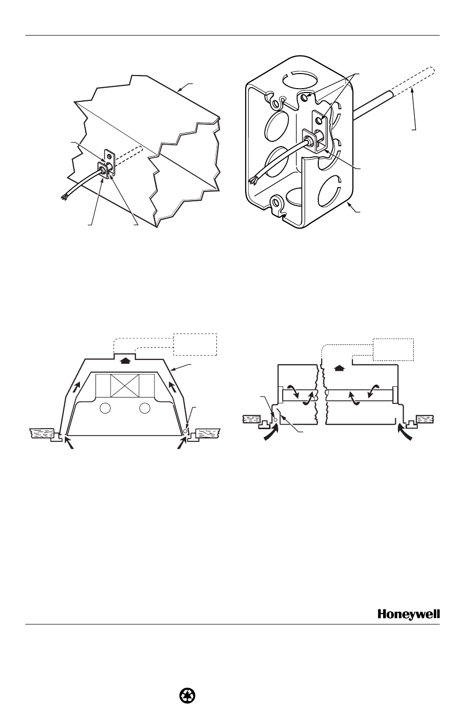
T7022A REMOTE TEMPERATURE SENSOR
Duct Mounting
DRILL 5/16 INCH
HOLE FOR SENSOR
(DRILL 3/8 INCH
HOLE IF EXTENSION
TUBE IS USED).
RETURN
AIR DUCT
SETSCREW
BRACKET
M17818
BOX MOUNTING
SHEET METAL
SCREWS
OUTLET BOX
MOUNTING
BRACKET
OPTIONAL
EXTENSION TUBE
M17819
Fig. 2. Duct mounting with mounting bracket.
Fig. 3. Duct or light troffer mounting
where wiring must be run in conduit.
Light Troffer Mounting
NOTE: Fig. 4 and 5 illustrate T7022 mounting for individual zone control. This type of application requires the use of
an M7034 Electronic Modutrol
®
Motor. In applications with an M7034, an S963 can be used to provide remote
setpoint adjustment, if desired.
Fig. 4. Cross section of light troffer showing a typical
mounting location of the side of the light troffer.
T7022
M17821
AIR
CHAMBER
DUCT
SHIELD
TO
DUCT OR
PLENUM
T7022
M17820
Fig. 5. Cross section of light troffer showing a typical
mounting location at the end of the light troffer.
CHECKOUT
Move set point above and below room temperature to
make sure controlled equipment operates properly. See
other system component instructions for additional
checkout procedures.
Home and Building Control Home and Building Control
Honeywell
Honeywell Limited-Honeywell Limitée
1985 Douglas Drive North
35 Dynamic Drive
Golden Valley, MN 55422
Scarborough, Ontario
M1V 4Z9
Printed in U.S.A. on recycled
60-0247√2 B.B. Rev. 2-01
paper containing at least 10%
www.honeywell.com/building/components
post-consumer paper fibers.